CAN Transmit
Overview
The CAN Transmit Tab provides a way to send out CAN messages that contain values from channels or special values such as firmware version or setup name.
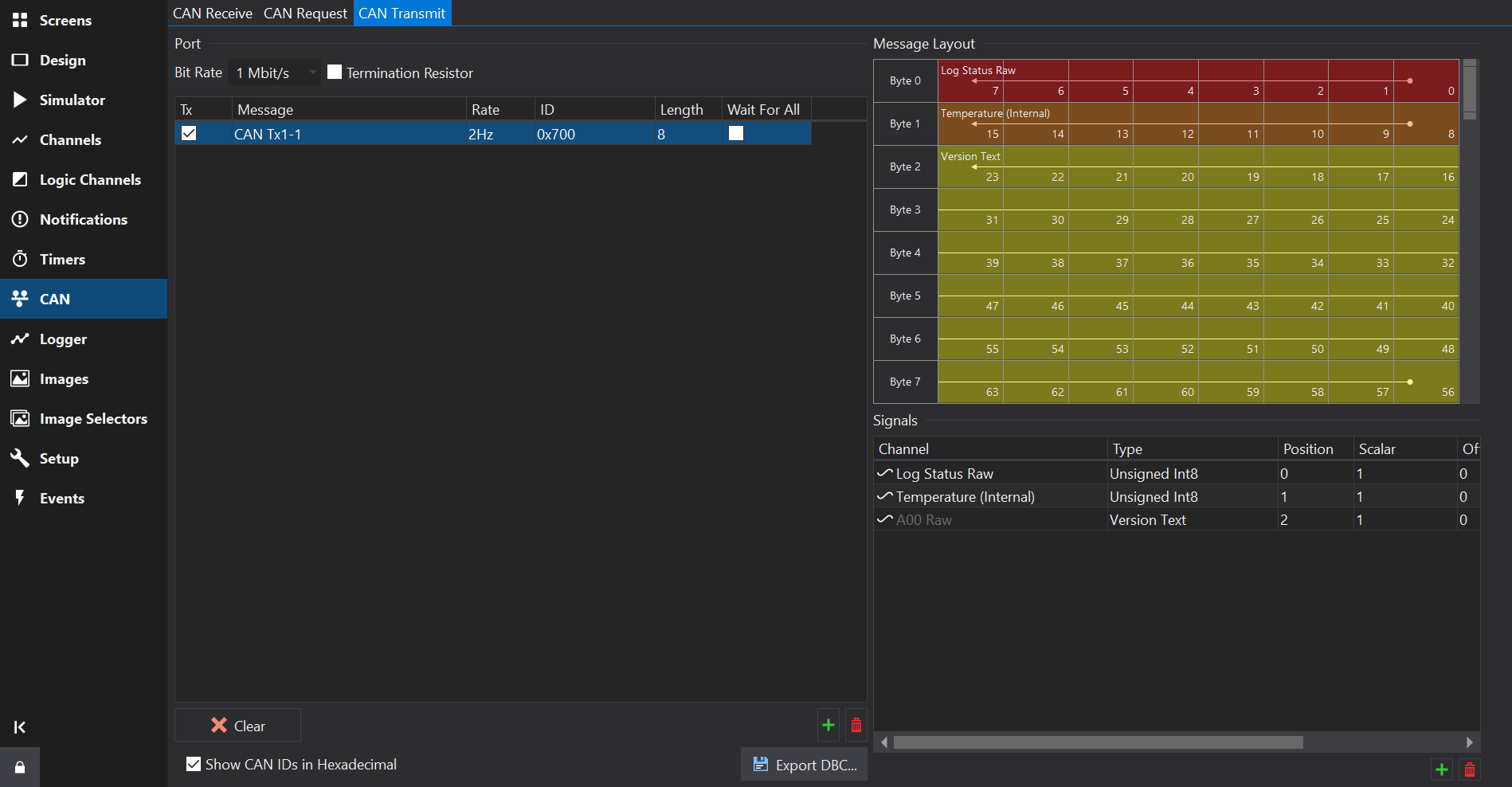
For displays with multiple CAN ports, select the port at the top-left of the tab. The port’s bit rate and other settings are described in CAN Bus Configuration .
If the Show CAN IDs in Hexadecimal box is checked, CAN IDs are shown and entered as hexadecimal numbers with an 0x prefix. Otherwise, they are shown and edited as decimal numbers.
Message Formats
Each message uses one of two formats, depending upon display and firmware support:
- Byte Aligned - signals are positioned at a byte offset within the message and use fixed-size data types.
- DBC - signals are positioned at any bit within the message and have a configurable bit length, encoding and byte order, in the same way as signals defined in a Signal Database (DBC) file. Counter and CRC signals are only available in DBC format messages.
The format of a message may be changed using the Format column while the message has no signals.
Messages
Adding or Removing Messages
Towards the bottom right of the Messages Table, use the  button to add a new message, and the
 button to remove the selected messages(s).
Use the Clear Port button to remove all CAN transmit messages from the selected CAN port.
Importing Channels
Click Import Channels… below the Messages Table to create messages from a list of channels. Select the channels to transmit, then choose:
- Data Type - the data type used for each channel’s signal (e.g. Unsigned 16-bit or Float 32-bit).
- Byte Order - Intel (little endian) or Motorola (big endian).
- CAN FD - create CAN-FD messages, for CAN-FD enabled ports.
- Starting CAN ID - the CAN ID of the first message created.
Signal positions are assigned automatically.
Importing and Exporting DBC Files
Use Import DBC… to import CAN transmit messages and signals from a Signal Database (.dbc) file. The DBC GenMsgCycleTime attribute is used to set the message rate. See also CAN Signal Database (DBC) Import
.
Use Export DBC… to export the CAN transmit messages to a DBC file, for example so that receiving devices can decode them. The exported signals use the DBC Scalar, DBC Offset, Export Units and Identifier settings described below.
Messages Table
Tx
Enables the message. If unchecked then the message will not be sent by the display; disabled messages are removed from the compiled display setup.
Message
Name of the message.
Format
The message format: Byte Aligned or DBC. See Message Formats.
ID
The CAN ID. This is specified as the right most 11 bits of a 16 bit value or the right most 29 bits of a 32 bit value for extended IDs.
Clicking on the header at the top of this column will sort the table by CAN ID.
If the number has 3 hexadecimal digits then it is a standard ID, if it has 8 hexadecimal digits then it is an extended ID.
When entering CAN IDs into this column, use the ‘S’/‘E’ button to switch between standard or extended.
Note that an extended ID with the same value as a standard ID is NOT the same message.
FD
Makes this a CAN-FD message. In FD mode, higher start bit values are possible. CAN-FD enabled CAN ports only.
BRS
For CAN-FD messages, sets the Bit Rate Switch flag so that the message data is transmitted at the CAN-FD data bit rate. CAN-FD enabled CAN ports only.
Rate
Rate at which the message is repeatedly sent, between 1Hz and the maximum rate supported by the display (e.g. 500Hz for CD6). In practice, high rates may not be achievable, in which case the message is sent as soon as possible.
Length
Specifies the Data Length Code (DLC) of the message, i.e. the size of the data packet of this ID in bytes. This can be anywhere between 0 and 8 bytes; by default it is set to the maximum size of 8 bytes. For CAN-FD messages this can go up to 64 bytes.
Wait For All
If the Wait For All column is ticked, then the CAN message will only be transmitted once all the inputs to the message are valid. Inputs such as analogue channels are valid immediately but for data coming via CAN or serial, the outputs are not valid until they have been received at least once.
If the Wait For All column is not ticked, then the message will be transmitted as soon as any input is valid.
Message Layout
When a message is selected, the Message Layout view shows the position of each signal within the message.
Signals
Adding or Removing Signals
A message must be selected in the Messages Table to be able to add signals.
Towards the bottom right of the Signals Table, use the button to add a new signal, and the button to remove the selected signal(s).
When adding signals, either select a Special Type (such as Display Serial Number, or a Counter or CRC for DBC format messages) or select one or more Channels. Positions are assigned automatically to the next free space in the message.
Use Import Channels… below the Signals Table to add several channels to the selected message at once.
Editing Multiple Signals
Multiple signals may be selected by holding down the Ctrl or Shift key while clicking on the signals. The selected signals may then be edited collectively using the signal properties form to the right of the tab.
Columns
Click Columns… to choose which columns are shown in the Signals Table and in what order. Columns may also be configured by right-clicking or dragging the column headers.
Highlighting
Signals without an input channel use a muted red highlight unless they contain a special/generated value, such as a serial number, version, counter or CRC.
Signals that overlap other signals in the same message are highlighted.
Signals Table
Channel
Channel that will be packed into the CAN signal.
Type
For Byte Aligned messages, the data type and byte order for the raw signal value. The data type affects the size of the signal.
Some data types are special and do not require a channel (e.g. Display Serial Number).
Warning
When using a special data type such as Serial Number, some display firmware versions still require a Channel to be selected or the transmitted signal value will be zero.
Byte Offset / Start Bit
For Byte Aligned messages, Byte Offset is the position of the first byte in the CAN frame that the signal occupies.
For DBC messages, Start Bit is the bit position of the signal, as defined in DBC files. See CAN Message Overview for more information.
Bit Length
For DBC messages, the length of the signal in bits.
Encoding
For DBC messages, the encoding of the raw value: Signed Integer, Unsigned Integer, Float or Double.
Byte Order
For DBC messages, the byte order of the signal: Intel (little endian) or Motorola (big endian).
Scalar / Offset (Inverse)
The inverse scalar and offset convert the channel’s physical value into the raw signal value:
Raw = (Channel Value * Scalar) + Offset
DBC Scalar / DBC Offset
The DBC scalar and offset decode the raw signal value into the physical value, as written to exported DBC files:
Phys = (Raw * DBC Scalar) + DBC Offset
Units Conversion
Units of the physical value, as used by the receiving device. If the input channel uses different units then Dash Design will insert additional scaling to convert from the Channel units to these units prior to applying the scaling.
Tip
By specifying the expected physical units here, if the source channel units are subsequently changed then the scaling change will automatically be accounted for, so the transmitted data should still be of the correct magnitude.
Export Units
Use the unit selector to choose the unit label written to DBC exports, without converting signal values. Leave blank to use the Units Conversion selection, or the source channel’s units if no conversion units are selected. Existing custom export labels remain supported.
Identifier
The signal identifier written to DBC exports. Use letters, digits and underscores, starting with a letter or underscore. Leave blank to use the generated identifier, which is shown greyed out.
Summary
Compact signal layout, data type, byte order and raw-to-physical scaling, followed by the export unit’s display label rather than its script identifier.
Counter and CRC Signals
DBC format messages may include Counter and CRC signals, which are generated by the display rather than coming from a channel. Select the signal and click Configure Signal… to configure it.
Counter Signals
| Setting | Description |
|---|---|
| Signal width (bits) | The size of the counter signal, from 1 to 64 bits. The signal must fit within the message length. |
| Start bit | The position of the counter signal within the message. |
| Byte order | Little Endian or Big Endian. |
| Shared counter name | Messages that use the same shared counter name share one counter. Leave blank to use a counter local to the message. |
CRC Signals
| Setting | Description |
|---|---|
| Signal width (bits) / Start bit / Byte order | The size, position and byte order of the CRC signal within the message. |
| CRC profile | The named CRC definition (preset) used by this signal. Presets may be shared between CRC signals; use New Preset…, Rename and Remove Preset to manage them. |
| Standard CRC | Selects a standard CRC parameter set (e.g. CRC-8/SAE-J1850, CRC-8/AUTOSAR, CRC-16/IBM-3740 (CCITT-FALSE)) or Custom. |
| Polynomial / Initial value / Xor-out (hex) | The CRC algorithm parameters. |
| Reflect input / Reflect output | The CRC algorithm reflection options. |
| Pad byte (hex) | The byte value used for padding. |
| Ordered byte ranges | The bytes of the message included in the CRC, in order. The start is inclusive and the end is exclusive. Negative offsets are relative to the message length (DLC) and an end of 0 means the end of the message. |
Model IPC Signals
For displays with a CDX Model processor, protected model IPC messages are hidden; a notice is shown when protected model IPC signals are present. See CDX Model .