CAN Transmit
Overview
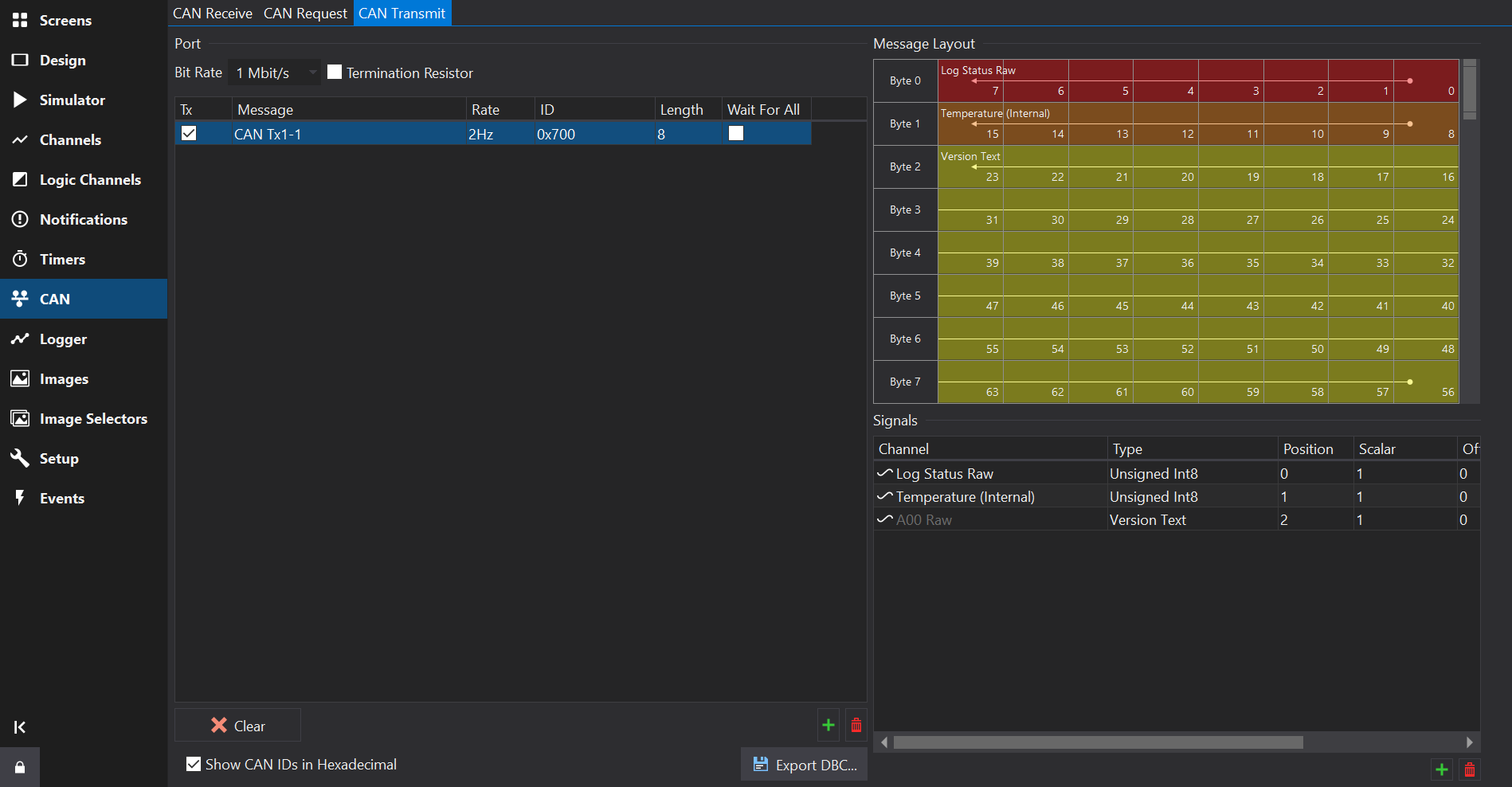
The CAN Transmit Tab provides a way to send out CAN messages that contain values from channels or special values such as firmware version or setup name.
Messages
Adding or Removing Messages
Towards the bottom right of the Messages Table, use the  button to add a new message, and the
  button to remove the selected messages(s).
Messages Table
Tx
Enables the message. IF unchecked then the message will not be sent by the display.
Message
Name of the message.
Rate
Rate at which the message is repeatedly sent.
ID
The CAN ID. This is specified as the right most 11 bits of a 16 bit value or the right most 29 bits of a 32 bit value for extended IDs.
If the Show CAN IDs as Hexadecimal box is checked, the IDs are shown and entered as hexadecimal numbers with an 0x prefix. Otherwise, they are shown and edited as a decimal number.
Clicking on the header at the top of this column will sort the table by CAN ID.
If the number has 3 hexadecimal digits then it is a standard ID, if it has 8 hexadecimal digits then it is an extended ID.
When entering CAN IDs into this column, use the ‘S’/‘E’ button to switch between standard or extended.
Note that an extended ID with the same value as a standard ID is NOT the same message and will not receive messages of the other ID type.
FD
Makes this a CAN-FD message. In FD mode, higher start bit values are possible. CAN-FD enabled CAN ports only.
BRS
For CAN-FD messages, sets the Bit Rate Select flag. CAN-FD enabled CAN ports only.
DLC
Specifies the Data Length Code of the channel, i.e. the size of the data packet of this ID in bytes. This can be anywhere between 0 and 8 bytes; by default it is set to the maximum size of 8 bytes. For CAN-FD messages this can go up to 64 bytes.
Wait For All
If the Wait For All column is ticked, then the CAN message will only be transmitted once all the inputs to the message (see below) are valid. Inputs such as analogue channels are valid immediately but for data coming via CAN or serial, the outputs are not valid until they have been received at least once.
If the Wait For All column is not ticked, then the message will be transmitted immediately; any sections of the message where the inputs are not valid will be zero.
Signals
Adding or Removing Signals
Towards the bottom right of the Signals Table, use the button to add a new signal, and the button to remove the selected signal(s).
A message must be selected in the Messages Table to be able to add signals.
Signals Table
Channel
Channel that will be packed into the CAN signal.
Type
Data type and byte order for the raw signal value. The data type affects the size of the signal.
Some data types are special and do not require a channel (e.g. Display Serial Number).
Warning
When using a special data type such as Serial Number, some display firmware versions still require a Channel to be selected or the transmitted signal value will be zero.
Position
Byte position of the first byte in the CAN frame that the signal occupies
Scalar
Scalar used to convert the Physical Channel value to a raw value. This is specified as if converting from raw => physical.
Phys = (Raw * Scalar) + Offset
i.e.
Raw = (Phys - Offset) / Scalar
Offset
Offset used to convert the Physical Channel value to a raw value. This is specified as if converting from raw => physical.
Units
Units of the Physical value. If the input channel uses different units then Dash Design will insert additional scaling to convert from the Channel units to the Physical units prior to applying the Scalar and Offset.
Tip
By specifying the expected physical units here, if the source channel units are subsequently changed then the scaling change will automatically be accounted for, so the transmitted data should still be of the correct magnitude.