Zero Channel
Overview
A Zero channel subtracts a captured offset from its primary input:
Output = Primary Input − Captured Value
When the reset input triggers, the current primary input value becomes the offset, making the output zero at that point. Subsequent changes are measured relative to that value. This does not reset or modify the primary input itself. For example, zeroing an input of 12 and then changing it to 15 produces 3. With no previously restored offset, the output follows the primary input until the first capture.
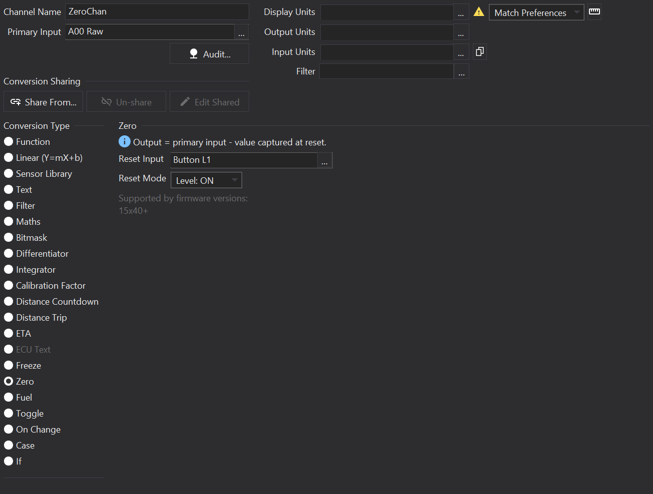
Options
Primary Input
Choose the value to zero in the channel editor’s common Primary Input field.
Reset Input
Choose the numeric source or channel that triggers capture of the primary value. The primary input must have received a valid value before a reset can capture it.
Reset Mode
- Rising Edge: capture when the reset input changes from zero to non-zero.
- Falling Edge: capture when it changes from non-zero to zero.
- Level: ON: capture on each reset-input update whose value is non-zero.
- Level: OFF: capture on each reset-input update whose value is zero.
The first reset-input value establishes the previous state for edge detection; it is not an edge. Level modes can capture on that first update. In level modes, the output continues tracking changes in the primary input between matching reset-input updates.
Supported By Displays
Only GLW-43 and LFRW-43 implement Zero channels, from firmware 15x40 (or 15d40) onwards. Other displays, including CD6, are not supported. Exported setups report each named Zero channel as a firmware-specific feature. Zero is a derived channel conversion, not a raw CAN signal conversion; create a separate channel to zero a received CAN value.
| Display | Supported? |
|---|---|
| CD34 | No |
| LDS4 | No |
| CD32 | No |
| LDS35 | No |
| LDS35_L | No |
| CD6 | No |
| GLW-43 | Yes |
| LFRW-43 | Yes |
| ZDU-L | No |
| ZDU-P | No |