CAN Receive
Overview
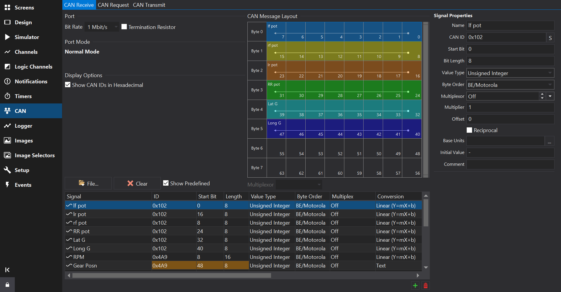
The CAN Receive Tab provides configuration of channels received via CAN messages.
At the bottom of the tab are the CAN frames and signals, represented as a unified list.
To the right of the tab is a CAN message layout view.
CAN Port
For displays with multiple CAN ports, the port may be selected via a drop-down box at the top-left of the tab. The signals table will only show signals configured for the selected port.
Differences to prior versions
CAN Receive setup differs from prior versions of the software and will automatically add a scaled ‘output’ channel for the CAN source, effectively combining the signal decoder and the scaling.
CAN channels will also be viible on the Channels Tab .
Signal Database (DBC) Import
Channels may be imported from Signal Database (.dbc) files using the Import… button. See CAN Signal Database (DBC) Import for further details on the import process.
It is not recommended to modify scaling after importing from a DBC file here - additional derived channels with different units / scaling may be added on the Channels Tab .
Adding or Removing Signals
Towards the bottom right of the Signals Table, use the  button to add a new signal, and the
  button to remove the selected signal(s).
New signals will copy some fields from the currently selected signal, such as the CAN ID.
Removing All Signals
Press the ‘Clear’ button to remove all CAN signals / messages from the selected CAN port.
Signals Table
The signals table lists all the CAN signals configured to be received on the selected CAN port.
The context menu (right click) provides a command to show the selected signal in the Channels Tab .
Signal
The name of the CAN source. Clicking on the header at the top of this column will sort the table by name.
If the signal was imported from a DBC file and a comment was specified then signal will have an information icon. Hovering over the signal will reveal the comment in a tool-tip.
Editing Multiple Signals
Multiple signals may be selected by holding down the Ctrl or Shift key while clicking on the signals.
Multiple selection allows editing of the selected signals collectively using the signals properties form to the right hand side of the view.
Some properties are not be available for editing in the properties form, for example channel scaling and filtering.
ID
The CAN ID. This is specified as the right most 11 bits of a 16 bit value or the right most 29 bits of a 32 bit value for extended IDs.
If the Show CAN IDs as Hexadecimal box is checked, the IDs are shown and entered as hexadecimal numbers with an 0x prefix. Otherwise, they are shown and edited as a decimal number.
Clicking on the header at the top of this column will sort the table by CAN ID.
If the number has 3 hexadecimal digits then it is a standard ID, if it has 8 hexadecimal digits then it is an extended ID.
When entering CAN IDs into this column, use the ‘S’/‘E’ button to switch between standard or extended.
Note that an extended ID with the same value as a standard ID is NOT the same message and will not receive messages of the other ID type.
FD
Makes this a CAN-FD message. In FD mode, higher start bit values are possible. CAN-FD enabled CAN ports only.
Start Bit
The start bit of the data. This is defined as the least significant bit of the least significant byte of the data. See CAN Message Overview for more information.
Length
The length of the data in bits.
Value Type
The type of the data. This can be one of the following values:
- Signed Integer
- Unsigned Integer
- IEEE Float
- IEEE Double
Byte Order
The byte order for multi-byte data. This can be either BE/Motorola (Big Endian) or LE/Intel (Little Endian). See CAN Message Overview for more information.
Multiplex
For non multiplexed data, this should be set to Off. Otherwise it can be set to Multiplexor if this value controls the multiplexing or a number (m=0, m=1, m=2 etc) which is the value of the Multiplexor at which this value is valid. See CAN Message Overview for more information.
Conversion
The conversion (scaling) type from the raw CAN data to a value or textual representation. Click the ‘…’ button to open a scaling editor.
Warning
If the signal was imported from a DBC file, and you want to change the scaling to a different unit then it is best to set the input units of the signal and a display unit or create a derived channel to rescale from the imported DBC values.
Scalar
Multiplier to convert from a raw signal value to a physical value.
Phys = (Raw * Scalar) + Offset.
Offset
Offset to convert from a raw signal value to a physical value (added to the value after multiplying).
Phys = (Raw * Scalar) + Offset.
Reciprocal
Not commonly used but changes the scaling equation to Phys = (Raw / Scalar) + Offset.
Base Units
Units of the scaled physical value of this signal. To convert to other units, add a channel on the Channels Tab and select a unit conversion after setting the input to this CAN channel.
Initial Value
Sets the initial value of the CAN output. This is the raw value. For example, for a CAN output of RPM_Raw used in an output to create RPM with a x2 scalar, the raw value for 2000 RPM would be 1000. To clear the initial value, set this to ‘-’. When importing from a dbc file, the “GenSigStartValue” attribute will be used to set the initial value.
Filter / Timeout
Filters may be applied to the CAN channel here such as controlling the behaviour when messages stop being received or providing an ‘Error Text’ value.
Aliased Signals
Signals that share the same bits and are not multiplexed will show a different background colour in the ID, Start Bit and Length fields. This is allowed but normally a configuration error; the colouring is intended to assist in spotting such errors easily. See the Gear Posn signal in the above screenshot for an example.
CAN message layout view
Selecting a signal in the signals table will display all signals in the same CAN frame (signals with the same CAN ID) in this view.
The Multiplexor drop-down box will be enabled if it is a multiplexed frame and will allow selection of one of the configured multiplexor values. When selected, this will only display signals in the view that are present when the multiplexor signal has this value.
For CAN-FD frames, the zoom-bar to the right of the CAN message layout view allows zooming and scrolling of the message view.