LEDs (Rule Based)
Overview
Rule based LED setups enable different LED configurations on different pages and complex LED patterns based upon a collection of rules.
Groups of rules may be defined that are active on a selection of pages.
Rules consist of an arbitrary list of conditions that each produce a pattern.
If multiple rules are active at the same time then they can be prioritised.
Active rules at the same priority level can be cycled through at an adjustable rate.
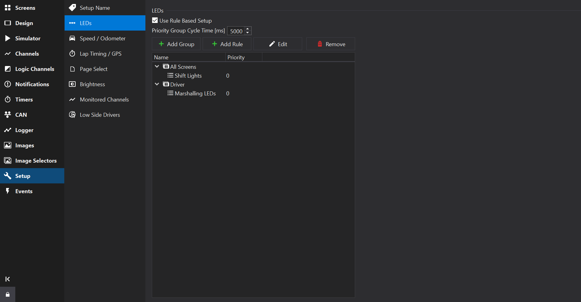
Main View
The main view shows a tree of groups and conditions; groups and rules are added and removed here.
Use the  Add Group to add a group.
Use the Add Rule to add a rule to the selected Group.
Use the  Delete button to remove selected groups / rules. The All Screens Group may not be deleted.
Use the  Edit button to edit the selected group or rule.
Rules and groups may be moved using drag & drop.
Use the context menu (right-click) to duplicate existing rules.
Priority Group Cycle Time
The Priority Group Cycle Time sets the time period at which multiple active rules of the same priority level are switched between.
Active rules at a lower priority level than another active rule may still have some effect if the active rule has not masked LEDs used in the lower priority rule. See LED Mask.
Groups
Rules within a group are only processed when the screen(s) it is assigned to are shown.
There is a default pre-defined group ‘All Screens’ which is active on every screen.
Named groups may be added and assigned to a selection of screens.
For example, you may add ‘Driver’ and ‘Diagnostic’ groups and only activate these on screens used by drivers or mechanics, respectively.
Use the Edit button to edit the selected group:

LED Group Editor
Group Options
Name
Sets the name of the group to express its intent or the set of screens it is associated with (e.g. “Driver” or “Diagnostic”).
Screens List
A list of screens is presented for which the group will be enabled.
Screens may be selected using the Edit button on the LED Group Editor.
Rules
Rules may be added to Groups and can be given names to express their intent (e.g. Shift Lights / Critical Fault).
Use the Edit button to edit the selected rule:

LED Rule Editor
Rule Options
LED Mask
Rules have an LED Mask. When a rule is active, the LED mask prevents any lower-priority rules from modifying the state of the LEDs that are set in the mask. In general it is best to set the mask to cover all the LEDs used by the various patterns in the rule. The mask may also cover unused LEDs that should not be lit by lower priority rules.
Priority
Higher priority numbers indicate a higher processing priority and are processed first by the display.
If multiple rules are active at a given priority level then the display will cycle through those rules at the rate specified by the Priority Group Cycle Time setting on the Main View.
Conditions List
Rules may contain multiple logical conditions that can each activate a different LED pattern (LED states). The conditions are processed in order, with subsequent conditions (if active) overwriting any LED states from the prior condition.
If any conditions are active within a rule, then the rule is considered ‘active’.
To the right of the conditions list are the condition properties.
Condition Properties
If multiple conditions are selected then the properties will act upon all of them.
Conditions may specify up to 2 channel comparisons, linked by a logical operator. If no comparators are selected then the condition is always active.
If a logical operator is not specified then only ‘Comparator A’ (if any) is evaluated.
Pattern
Defines an LED pattern to display when a condition is active.
Click the … button on the LED Pattern Picker to open the pattern editor:

LED Pattern Picker

LED Pattern Editor
The LED Pattern Editor lists all LEDs available for configuration.
A fixed colour may be selected for each LED. Alternatively if a ‘Colour Channel’ is selected then the colour may be controlled by the channel value.
If a flash rate is configured then the LED will alternate between ‘Colour’ (or Channel based colour) and ‘Flash Colour’ at the given rate.
Selecting multiple LEDs allows their properties to be set collectively.
Interpolated Patterns
If the Pattern Mode property is set to Interpolate for a LED condition, then a channel may be selected to interpolate the state of LEDs in the selected pattern. This can be used to create shift light patterns without manually entering multiple conditions, which would otherwise be a time consuming process for a common use-case.
Interpolation only occurs over LEDs that are not configured in the pattern (i.e. have their colour set to ‘OFF’ and do not have a Colour Channel).
‘Right to Left’ will cause interpolated patterns to start from the right hand side as the starting point.
‘From’ and ‘To’ define the input channel value that signifies the beginning and ending of the interpolation range for the input channel. When the input channel is equal to the lower limit then no LEDs in the pattern will be shown. When the input channel reaches the ‘To’ value then all LEDs will be shown in the pattern.
‘From’ and ‘To’ may be reversed where To > From, in which case more LEDs will be shown as the input value decreases.
Interpolation may be used in conjunction with conditions.
Bit Patterns
If the Pattern Mode property is set to Bit Pattern for a LED condition, then a channel may be selected who’s individual bits correspond to LEDs.
Each bit in the input channel will correspond to LEDs that have been assigned a colour in the LEDs property. The first LED with a colour (i.e. not set to OFF) will be bit 0 and the next enabled LED will be bit 1 etc.
‘Right to Left’ will cause bit patterns to start from the right hand side; thr right-most LED that has a colour defined will correspond to (bit 0) in the input channel.
Dash Design will create hidden Bitmask Channel s to drive each LED individually.
The input channel will be converted to an integer representation prior to masking; the display uses 64bit floating point for channel values internally, giving exact conversions for up to 52 bits.
Colour Channel
Channels may be used to select the colour of an LED. The colour selected by the channel value depends on the display type, but for current displays the following table is used:
| Value | Colour |
|---|---|
| 0 | Off |
| 1 | Red |
| 2 | Green |
| 3 | Blue |
| 4 | Orange |
| 5 | Magenta |
| 6 | Yellow |
| 7 | Cyan |
| 8 | White |
| 9 | Channel (Direct Drive) |
| 10 | Channel RGB111 (Direct Drive) |
The RGB111 colour space is a 3-bit colour space with 1 bit per colour channel (Red, Green, Blue), meaning that input channels have a different colour mapping and should be in the range 0-7.