Pinout
The Pinout view displays ECU pinout information in a table with a connector diagram. For how to add objects see the Adding an Object section.
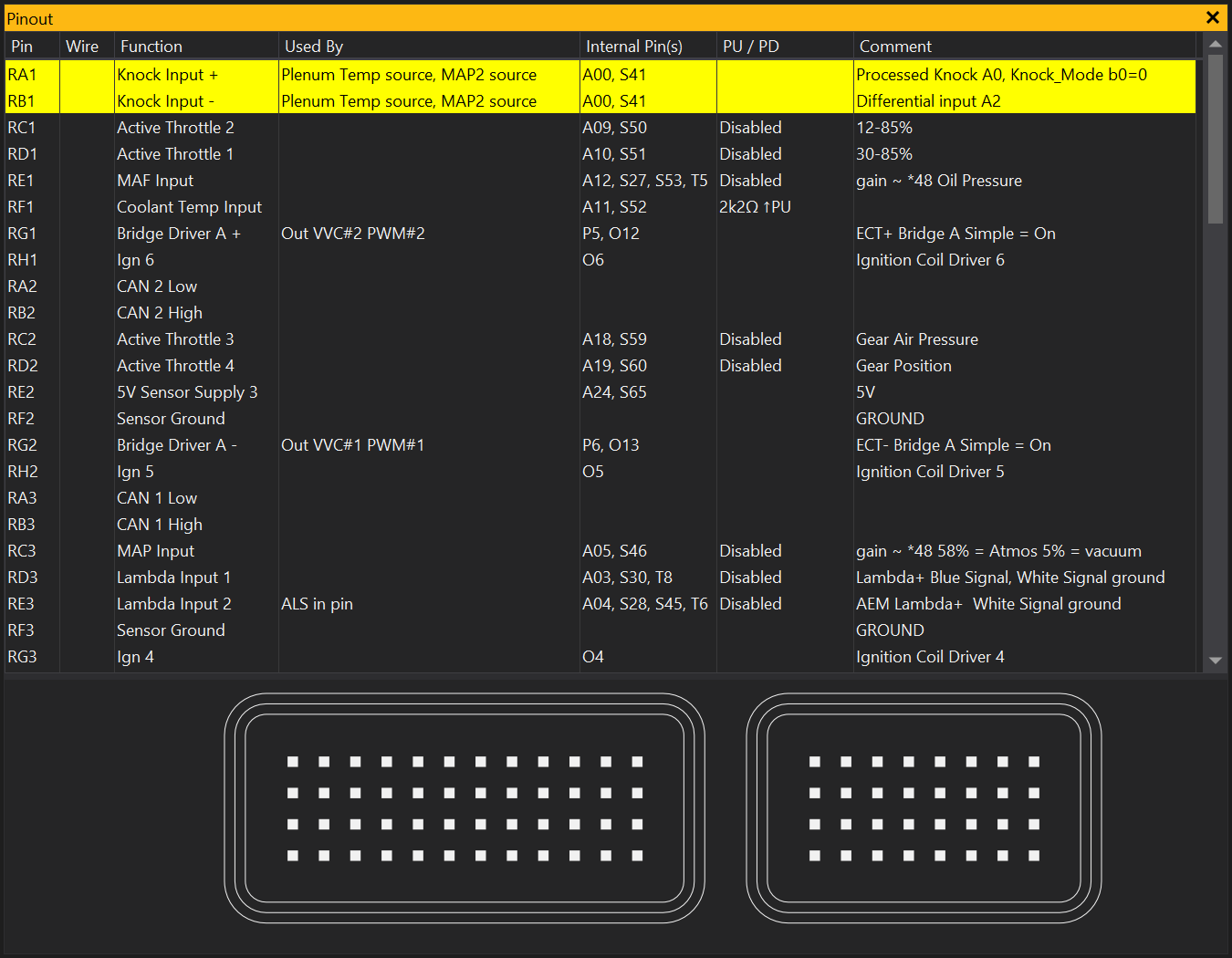
The table and diagram are linked:
- Selecting pins in the table highlights those pins in the connector diagram.
- Clicking pins in the connector diagram selects the corresponding row in the table.
Quick start
- Add a Pinout view to your layout.
- Confirm the ECU has loaded EDX files with pinout data.
- Click a pin in the diagram or select a row in the grid.
- Check Used By, Internal Pin(s) and PU / PD to verify routing and pull resistor setup.
- If needed, right-click the view and use the ECU definition extension management actions.
Grid columns
Pin
External connector pin ID (for example RA1, RB1). This comes from the pin id value in the pinout definition.
Wire
Wire identification/visual information for the pin. In the grid this is shown as text and/or coloured wire styling, based on the pin wire definition (for example wire text, colours, and pattern).
Wire styling can be overridden per-pin in the grid. Right-click the cell and select Configure Wire Style… to edit the wire pattern for that pin. Right-click and select Clear Wire Style Override to remove any override and revert to the default wire style.
The styling override is saved in the calibration file.
Note that this information is not stored within the ECU itself, so it is recommended to use the ‘Open matching calibration when connected" setting in the Port “Additional Settings”. Or use the menu command.
Function
Human-readable function label for the pin (for example sensor input or output purpose). This comes from the pin func field.
Used By
A comma-separated list of ECU options/functions currently using that pin, calculated at runtime from the active calibration and pin routing definitions.
This is calculated by combining:
- direct routing matches from option values against the pin’s internal IDs (
a2d,pwm,out_pin,swt,swt2,timer), and - conditional
used_ifrules defined on the pin (option-based or expression/script-based).
If more than one active route/use is found, the pin is treated as a conflict (highlighted in the grid). Script evaluation errors are reported via the Comment column.
Internal Pin(s)
Internal ECU signal IDs associated with the external connector pin. This is a compact list built from the pin’s internal mapping fields:
Axx= Analog input (a2d)P#= PWM channel (pwm)O#= Output pin ID (out_pin)S#= Switch input ID (swt/swt2)T#= Timer ID (timer)
So values like A09, S50 mean that external pin is mapped to analog input 9 and switch input 50 internally.
Hover this column to see expanded tooltip text (for example A2D A09, Switch S50).
PU / PD
Pull-up / pull-down resistor state/value shown for the pin:
- Positive value = pull-up (
PU) - Negative value = pull-down (
PD) - Zero = none/disabled
This can be either fixed or configurable:
- Fixed: numeric
pullupvalue in the pin definition. - Configurable: script
pullupexpression in the pin definition (evaluated at runtime from calibration state).
If a pin references an a2d and does not define its own pullup, the pullup can be inherited from that A2D definition.
Comment
Pin comment text from the pin comment field. If there is a routing/pullup/used_if script error, the error text is shown here so issues are visible directly in the grid.
Conflict and warning colours
When the pin routing is ambiguous or invalid, row highlighting helps identify issues quickly:
- Red: script/runtime error while evaluating pin routing logic.
- Orange: output pin conflict (multiple active output uses).
- Yellow: non-output conflict (multiple active uses, commonly shared inputs).
Where this information comes from
Pinout data comes from ECU Definition Extension (EDX) files.
For this view, the key EDX structures are:
connectors->sections->pinsfor connector layout and per-pin fields (id,func,wire,comment,a2d,pwm,out_pin,swt,swt2,timer,pullup,used_if)a2ds,timers,switches,pwmsfor internal ID metadata used by routing/pin interpretation
If no relevant pinout content is present in loaded EDX files, the view shows a “No pinout information available” message.
Troubleshooting
“No pinout information available”
This means no usable pinout connector/pin data was loaded from EDX content. Check that:
- the correct EDX is available for your ECU definition/calibration
- the EDX actually contains
connectors/sections/pins - the expected EDX is being loaded (including include/override order)
Used By is empty or unexpected
- Some pins are intentionally unassigned in a given configuration.
used_ifconditions may currently evaluate false.- Routing options may not be set to the pin’s internal IDs.
- If comm code links are used, underlying channel references may not intersect as expected.
Pullup value looks wrong
- Check whether pullup is fixed numeric or expression-based in EDX.
- For A2D pins, remember pullup may be inherited from the A2D definition if not explicitly set on the pin.
- Expression errors are surfaced in Comment.
Related topics
View Properties
Properties editable via the properties editor.
| Property | Script ID | Description |
|---|---|---|
| Title | title |
The title of the window. |
| Script ID | id |
The scripting ID of the window. Can be used as an alternative to the title for searching for windows from scripts. |
| Tool Tip | tooltip |
Window tool tip. |
| Splitter Position | split_dp |
Splitter position (in dp) |
| Stretch Column | stretch_column |
Column index to stretch in the grid, -1 means no column is automatically stretched |
| Column Widths | column_widths |
Comma separated list of column widths in device independent pixels, e.g. 100,200,300 |