Crank Sensor
Overview
The crank sensor is used to determine the position of the crankshaft and the speed of the engine. The crank sensor is usually mounted on the engine block and reads a toothed wheel mounted on the crankshaft. It may be used in conjunction with a camshaft sensor to determine the position of the engine cycle.
Sensor Type
The crank sensor is usually a Hall effect sensor or a VR (Variable Reluctance) sensor. The sensor is connected to ECU timer T1 which has a software selectable pull-up resistor.
| Sensor Type |  T1 Pull-up T1 Pull-up |
|---|---|
| Hall Effect / Optical | Yes |
| VR / Inductive | No |
Edge Selection
The ECU man be configured to select which edge of the signal is used to interrupt the ECU for engine position related processing, these options may be named differently on some ECUs:
- Crank Rising Edge or T1 Rising Edge
- Crank Falling Edge or T1 Falling Edge
VR sensors have one direction edge that is sharply defined. In the other direction, there are 2 edges and they are slower. Selecting the correct edge here is crucial to ensure accurate engine position detection.
    xychart-beta
    title "VR Sensor Pulse"
    x-axis [0, 1, 2, 3, 4, 5, 6, 7, 8]
    y-axis "Voltage" -5 --> 5
    line [0, 0, -0.3, -3, 3, 0.3, 0, 0, 0]
An oscilloscope can be used to determine the best edge to use. The sensor output should be monitored while running / turning over the engine to determine which edge is the most sharply defined.
To verify that the correct edge has been selected, it is recommended to record an ECU internal data log with the crankshaft moving at a constant rate. It is expected that the synchronization strategy and  Tooth Control table have been configured before this test.
| Channel | Description |
|---|---|
 A Tooth A Tooth |
Actual teeth feed into to Tooth Control table. |
| Wheel Tooth |
Decoded internal tooth number, increments up to the value of Wheel Teeth. |
| Fuel Tooth No |
Decoded internal teeth for engine cycle, decoded by Tooth Control table used for fuelling, increments up to the value of Fuel Teeth.. |
| Ign Tooth No |
Decoded internal teeth for engine cycle, decoded by Tooth Control table used for sparking, increments up to the value of Spark Teeth.. |
| MX Tooth Time |
Time interval between actual teeth; i.e. time separation between crank interrupts. |
| Tooth Time |
Time interval between internal teeth decoded by Tooth Control table. The most important measurement in ECU. |
The following images show the difference between the correct and incorrect edges for a VR sensor:
Incorrect Edge
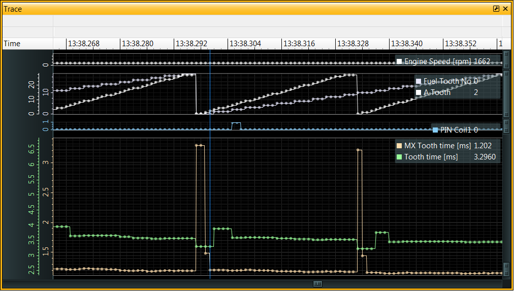
See the long tooth interval detected in MX Tooth Time when A Tooth = 0
The long tooth appears to be in 2 parts of 3.296 and 1.482 ms, with the regular teeth spaced at 1.185 ms.
This is from a 30-2 wheel so the missing tooth interval should be approximately 3x the regular teeth interval.
Notice that the Tooth Time channel has major discontinuities; it is expected that the internal teeth (decoded by the tooth control table) are regularly spaced and so a more constant value is expected here.
Correct Edge
With the Crank Rising Edge and Crank Falling Edge swapped we get just a single long MX Tooth Time 3.754 ms, equal to 3 regular teeth (on a 30-2 wheel) as expected. The regular teeth are spaced at ~1.243 ms:
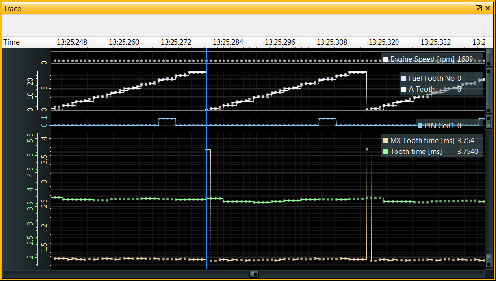
3.754ms / 1.243ms = 3.02 teeth
Also notice that the Tooth Time and A Tooth channels are smoother, meaning that the edges are interrupting the ECU more reliably.
If you are unable to start the engine and idle, it is possible to get the timing wheel running at a steady speed by removing the spark plugs (to avoid compression) and using the starter motor to turn the engine over. This will allow the ECU to log the crankshaft position data without the engine running. For safety, any injection and spark outputs can be disabled in the ECU calibration for this test.
Crankshaft Position Sensor Filtering
Hardware Filtering
- T1 Filter Below - RPM value below which the T1 filter is active.
- T1 Low Sens Above - Reduces the sensitivity of the T1 input above this RPM value, can be useful for VR sensors.
- Crank Filter - Time window, in microseconds, for filtering edges on the crank sensor input.
Software Filtering
- Tooth Short Ignore - Enables software filtering of short tooth intervals. This is useful for filtering out noise on the crank sensor input.
- Tooth Short Running - This is a percentage of the last valid actual tooth interval, edges detected that are less than this percentage are rejected.
- Tooth Short Start - When cranking (starting) the engine, before synchronization is achieved, Stat Sync'd == OFF, software filtering uses a fixed time interval for rejecting edges - edges detected that are less than this interval will be rejected.
When running, Tooth Time x Tooth Short running is used to determine the minimum tooth interval that will be considered a valid tooth event.
The calculated value for the short tooth test is stored in A Tooth Short Test.
If a short tooth is detected, it will record this information in:
- A Tooth Short [ms] - captures captures MX Tooth Time
- A Tooth Short No - captures A Tooth
- A Tooth Short Rev - captures Cam count MX
This information will be recorded regardless of whether Tooth Short Ignore is set.