Calibrations are at the core of GWv4. The majority of ECU’s that GWv4 can connect to contain calibration data, for example a Fuel Map for an engine management system.
Calibrations can be downloaded from the ECU, manipulated either on or off-line and saved to the PC. This allows a library of calibrations to be built up for uploading into the ECU.
To start a new calibration click the button on the tool bar, or from the main menu select New Calibration.... You will be given a list of the current ECU’s types and versions installed, select the ECU and version you want to start the new calibration. This will create a new blank calibration.
We would recommend that a base map is used as a starting point rather than a blank calibration. You can download calibrations from the GEMS website: gems.co.uk/downloads, or by contacting GEMS directly on info@gems.co.uk
Editing a Calibration
Editing a calibration is done by modifying the maps, tables and options. This is achieved using the map, table and option objects which display them. For details on how to display and edit these, see the Views section.
Editing Offline
When you are working offline (not connected to an ECU) changes you make to the calibration are saved to the current file. These changes can be saved to the ECU by Programming a Calibration.
Editing While Online
When you make changes while you are online (connected to an ECU) these changes will be sent to the ECU but not saved permanently. This means that if the ECU is turned off it will not remember to changes when turned back on. To permanently save to changes to the ECU you need to ‘Store Changes’. Do this by selecting Store Changes in ECUCtrl+K from the main menu. You can set GWv4 to do this automatically store changes periodically by selecting Auto Store.
Undoing Changes
As changes are made to a calibration, GWv4 keeps a record which is maintained until another calibration is opened or GWv4 is closed.
To undo changes:
Select UndoCtrl-Z, press Ctrl+Z, or click the button. This will undo the last change made. Repeating the process undoes the previous change and so on. If a change affected several sites, for example a percentage change on an area of the Fuel Map, then all the site changes will be done in one process.
Undone changes can be redone. To redo the last change undone:
Select RedoCtrl-Y, press Ctrl+Y, or click the button. In addition to the button illuminating when the calibration is changed, “[modified]” is then displayed in the title bar.
Undo History
All recent changes made to the calibration can be viewed as a list, allowing you to revert to an earlier state of the calibration. When you select an earlier state, all changes made since then will be undone. To view the undo history, from the main menu select HistoryCtrl-H. The undo history window will then be shown:
The changes made are listed from oldest to newest with newest with at the bottom. To revert to a specific state, simply click on the line in the history you want to revert to and all changes back to that point will be undone.
Programming a Calibration
Programming a calibration loads a selected calibration file into the ECU. If you are working offline then GWv4 will attempt to connect to the current ECU.
Send current calibration
To program the calibration currently open with GWv4, from the main menu select Send Current Calibration, or click the ‘Send Current Calibration’ button on the toolbar.
Send Recent/Selected Calibration
To program a calibration to the ECU which is not the currently open calibration, then from the main menu select Send Calibration to ECU..., or click the ‘Send Recent Calibration’ button on the tool bar. Clicking the small down arrow next to this button will display a list of the calibrations which have been opened recently.
Storing Calibration Changes Permanently
Overview
When calibration changes are made whilst the ECU is connected to GWv4, the changes are sent to the ECU and it will operate using those values, but the configuration may not saved permanently.
To make the changes ‘permanent’, the ECU must copy the RAM ‘shadow copy’ into ’non-volatile memory’ (NVM) - typically either EEPROM or Flash memory.
Unless the changes are copied to NVM, when the ECU is powered on again, it will load the prior NVM contents into RAM - losing any changes from the prior session. This behavior is dependent upon the ECU type and configuration.
Auto Store
Auto Store, controlled by option Auto EE, is a switch that controls whether the ECU will automatically save changes to non-volatile memory. This feature is accessible from application menu Auto Store.
If modifying the calibration of an ECU that does not have Auto Store enabled, GWv4 will post a notification to inform that Auto Store is disabled.
Tip
It is best to turn Auto Store OFF when the calibration process is completed and the ECU is not being actively tuned, taking care to ensure that the calibration has been stored to the ECU and backed up on the PC. This will guard against any accidental changes in the field, for example due to an unexpected program error that could corrupt the calibration RAM. If Auto Store is OFF then the ECU is more likely to recover itself following a power cycle.
Storing Changes Manually
If Auto Store is OFF, then the ECU will not automatically save changes.
Using the Store Changes in ECUCtrl+K command will instruct the ECU to save any changes into non-volatile memory.
ECU Storage Status
If the ECU detects that its RAM copy of the calibration does not match the non-volatile copy, EE will be displayed in the application status bar. The term EE is derived from EEPROM.
The Error EE Checksum channel will be set to ON if the ECU detects that there is un-stored calibration data.
While the ECU is programming the non-volatile memory, the Stat Prog EE channel will be set to ON.
Warning
If the ECU is powered off during the programming of non-volatile memory, the ECU may be left in an inconsistent state. It is best to first close the connection and GWv4 will check that the ECU is in a safe state to be powered off.
Password Protection
Some ECUs have security features built in that allow calibrations to be password protected. If an ECU supports security, the Set Password... and Clear Password... menu items are enabled in the ECU menu. A padlock icon appears in the status bar to show the status of the secure ECU. If another computer is used to connect to a password protected ECU, the password must be entered before the calibration can be downloaded or edited. If the password is not known, the calibration must be erased from the ECU to allow access to the ECU.
Set a password
Connect to the ECU.
Select Set Password....
A dialog box appears prompting for a password. The password must be 6 characters long and can contain any alphanumeric character.
Enter the password and click ‘OK’.
Clear Password
Once connected to a password protected ECU, the password may be cleared. Clearing the password removes the security such that any PC can connect to this ECU.
To clear the password:
Connect to the ECU. You will be prompted for the current password.
Select Clear Password....
If the password is not known and you wish have access to the ECU, you can do this by clearing the current calibration. Connect to the ECU, when prompted for the password, select ‘Clear Calibration’. This will clear the calibration in the ECU allowing a new calibration to be uploaded.
Comparing Calibrations
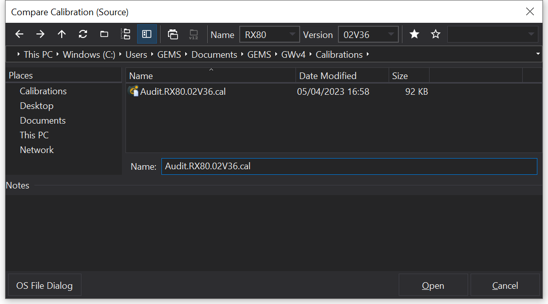
Comparing calibrations enables you to compare the currently open calibration to another calibration of your choice. To compare calibrations, from the main menu select Compare Calibration... ( ). This will display the following file dialog:
Here you can then select a ‘Source’ calibration, that you can compare your currently open calibration to.
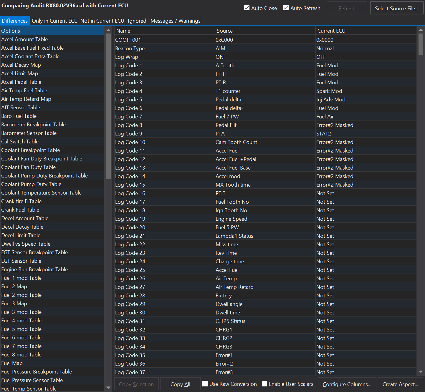
When you have selected the file click ‘Open’. A new “Comparison” tab will display that shows a list of all the differences between the two calibrations:
The differences will display all groups of values which are different. Select an item from the differences list on the left hand side to view. The main window will then display each individual value which are different.
Only/Not In current ECU
This will display a list of all the differences where value does not feature in either the current calibration, or the compared calibration. This may occur for example when a new option is added to a later version of ECU.
Ignored
Some items are not included in the comparison, these items will be listed here.
Messages/Warnings
Any message that was created during the calibration [convert process](/calibrations/converting-a-calibration.html#Converting a Calibration) will be displayed here.
Configuring Columns
This allows you to add extra ways to compare the differences. For example; if we want to display the actual difference in value between the two; Click on the ‘Configure Columns’ button, then click the ‘Add’ button. Then from the ‘Predefined’ list, select ‘Difference’, and click ‘OK’. The difference between the two value will now be displayed in a new column.
Note
It is possible to create your own calculations, this feature is still in Beta, please contact GEMS for more details.
Copying Values
Values may be copied from the file to the current ECU opened by GWv4.
Copy Selection will copy the values on the rows selected in the right hand pane from the source file to the current ECU (the connected ECU / the file opened in GWv4).
The ‘Use Raw Conversion’ check box causes the actual raw value to be copied between the ECU’s. Otherwise the value is converted to a scaled value in the context of the source ECU and assigned as the scaled value in the destination ECU.
Changing the source file
To quickly change the comparison to compare a new file, click the ‘Select Source File…’ button in the top right and select the new file to compare with.
Auto Refresh
Selecting Auto Refresh will cause the comparison to be re-evaluated when values are changed in the ECU. If Auto Refresh is disabled, then you can manually get the compare to be re-evaluated by pressing the ‘Refresh’ button.
Converting a Calibration
Converting a calibration may be required when upgrading the firmware in a GEMS ECU.
Converting a Calibration
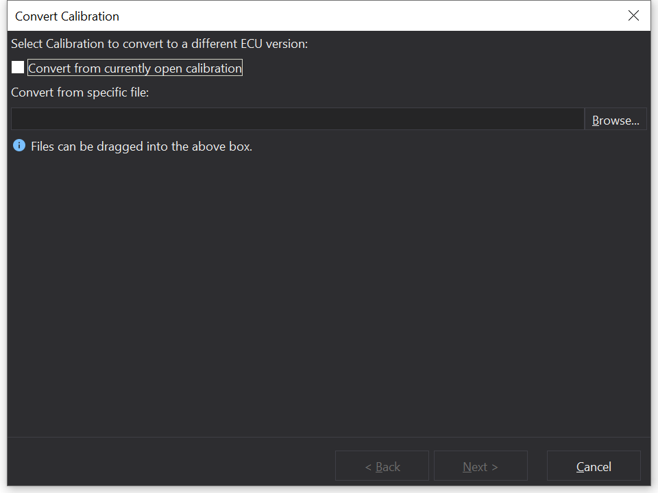
To convert a calibration select Convert... This will display the following window:
The currently open calibration can be converted by simply ticking the ‘Convert from currently open calibration’ box.
Alternatively you may wish to convert a previously saved calibration, to do this select the ‘Browse…’ button, and navigate to and select the calibration you wish to convert. Or you can simply drag and drop the calibration from your files into the text window.
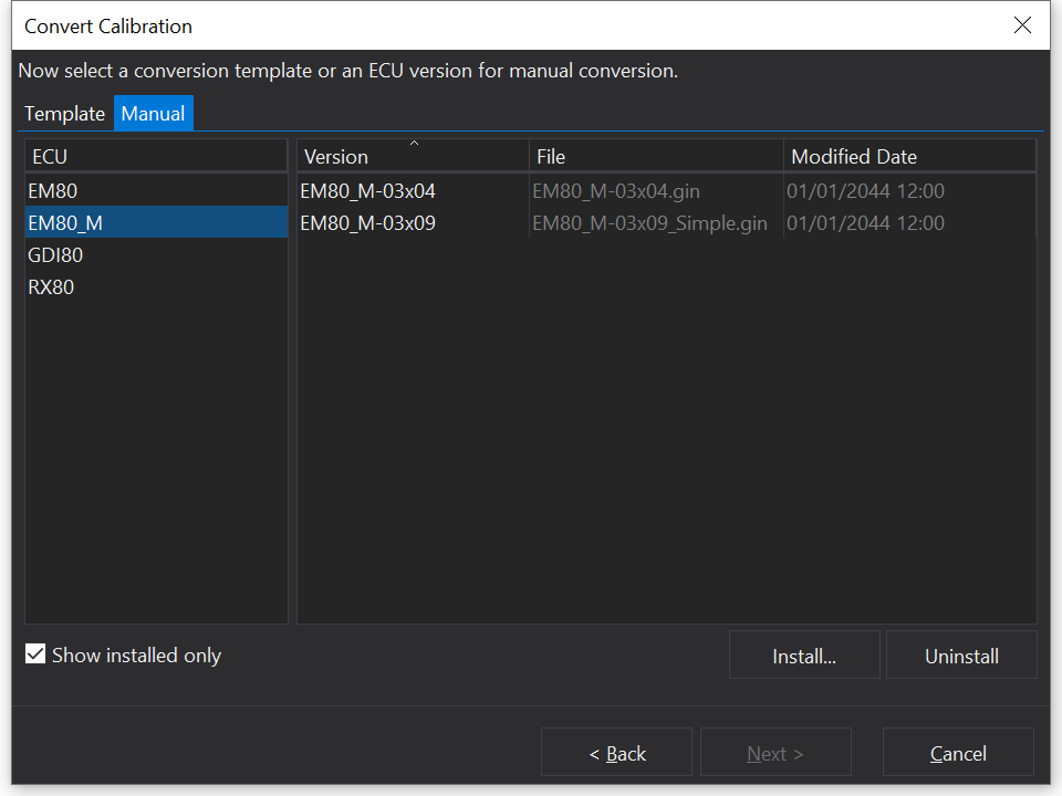
Select ‘Next’ and something similar to the following window will then be displayed:
You will automatically be on the manual conversion tab, on the left side of the window are a selection of ECUs the the calibration could be converted to match. If the calibration is specific to a particular ECU then that ECU will already be selected.
The right side of the window displays various versions of each ECU. By default only installed versions will be displayed, but this setting can be turned off by the small tick box at the bottom left of the window.
New versions can also be installed using the ‘Install…’ button towards the bottom right of the window, and old versions can be uninstalled using the ‘Uninstall’ button in the same location.
Manual Conversion
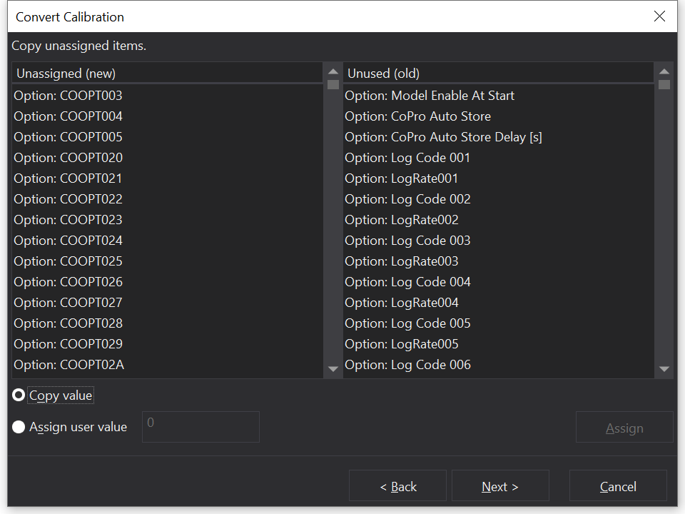
Once the target version has been selected, simply select the ‘Next’ button, and the following window will be displayed:
On the left are new options/channels etc that do not exist in the currently open calibration. These new options/channels will need values assigned to them. This can be done by copying a value from the right column across to the new options/channels, or by assigning a user value.
On the right are old/unused options/channels that exist in the currently open calibration, but not in the template that is being used to convert.
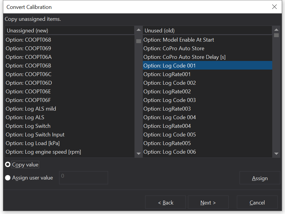
Copying Values
At the bottom left of the window the copy option should be selected by default, if not then simply select the radio button. Now select the new item from the left list to take the value of the old item from the right list. Once both are selected click the ‘Assign’ button at the bottom right of the window. Both selected items will disappear from the lists as the old item is assigned to the new. An example copy is shown below.
Assigning New Values
If none of the old items are a match for the new items, then you may want to manually enter a value for the new items. To do this select the ‘Assign user value’ radio button in the bottom left of the window. Once selected there is a text box next to the radio button which you will now be able to type in.
Select a new item from the left list, enter a value in the text box to assign to it, then simply click the ‘Assign’ button and the new item will disappear from the left list as the user value is assigned.
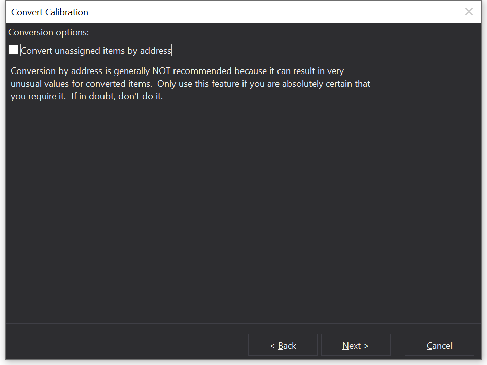
Once all new items have had values assigned to them, or have been left with a default value, simply select the ‘Next’ button.
If there were new items that were left unassigned, then the following window will be displayed.
Otherwise, if all items had a value assigned to them, then something similar to the following window will be displayed.
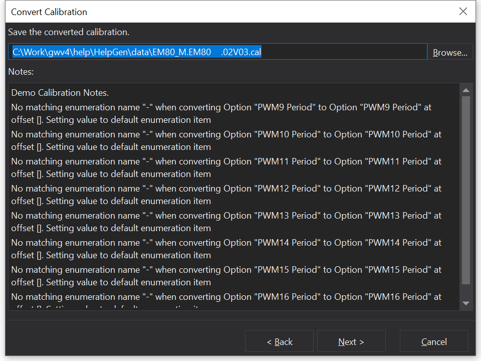
Adding Notes and Saving
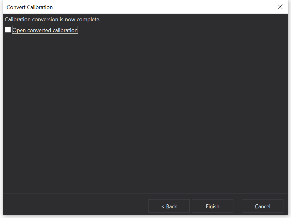
Here you can add some notes about the calibration, such as details about important setting in the calibration. These notes can be used to quickly identify calibrations with similar names. The calibration can then be saved, and the following window will be displayed.
The new calibration can then be opened immediately, or original calibration that you were converting from can be left open.
Template Conversion
Conversion templates allow you to easily convert between two ECUs. When creating a conversion template you will be able to select options, tables, and maps from the old ECU and assign these values to new parameters in the new ECU.
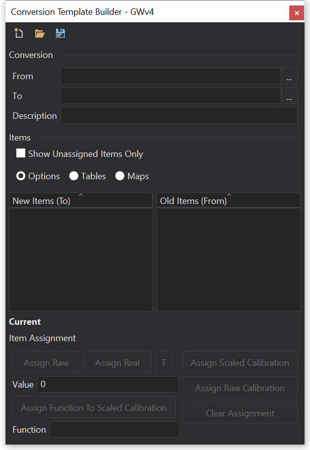
It is possible to create a conversion template from within GWv4, this is done via selecting Build Conversion Template..., upon which the following window will be displayed.
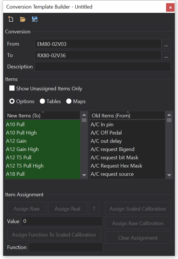
From here you can either choose to load an existing template, or to create a new template. To start creating a new template, simply add a From and To ECU definition.
Once the From and To ECU definitions have been selected, you will see that there are two corresponding lists from each ECU. By default these will show Options first, but you can simply select Tables or Maps. Here you can select to assign completely new values, or you can select to assign one of the old items to one of the new items.
A description for the conversion template also needs to be entered, and then the template can be saved.
The conversion template will then appear in the templates section of the standard calibration conversion window when you select a source ECU that is the same as the template source.
Live Trim Control
Overview
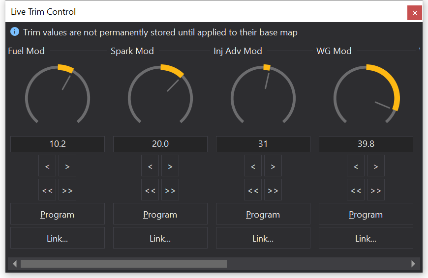
The Live Trim Control gives easy access to modifier channels. To display is, select Live Trim ControlCtrl-T from the main menu.
Modifier channels globally adjust the output value of a map but not permanently.
This allows you to find an appropriate value before changing the base map.
For example, Fuel Mod will adjust the value obtained from the Fuel map. Once you find an appropriate fuelling value, you can program the map at the current site.
You can adjust the modifier by using the knob (drag up or down with the mouse). Or you can use the arrow buttons. The double arrow buttons make a large increment or decrement to the modifier.
To program the modifier into the map, click the ‘Program’ button. This will apply the modifier and reset the modifier channel to zero.
Warning
The modifier channels are not saved with the map. If you close the calibration, the modifier channels will be reset to zero.
Note
The Live Trim Control feature was formally known as the Virtual Pot Box.
Linking to an external controller device or the mouse wheel
The modifier channels displayed by th Live Trim Control can be linked to either a GEMS USB ‘Pot-Box’ controller, a MIDI controller or to the mouse wheel.
To set up such a link, press the ‘Link…’ button.
To link to a USB controller, select ‘Link to USB Pot Box’. This will then display the ’link to controller’ dialog
This can alternatively be done by right clicking on the large dial in the Live Trim Control window and selecting ‘link to controller’ from the menu.
Press one of the encoder dials on the Pot Box to set up the link.
To link to the mouse wheel, select ‘Link to Mouse Wheel’.
This will take over control of the mouse wheel until the Live Trim Control window is closed or if the currently open calibration is closed.
Once linked, you can unlink from the mouse wheel by pressing the link button again, which should now be labeled ‘Unlink’.
Scrolling the mouse wheel will adjust the modifier. Pressing the wheel will program the current map site with the modification.
The software also supports MIDI controllers. Specifically the “Behringer X-TOUCH Mini” has custom integration and works well with the software in either Normal or MC modes.
If the mouse wheel doesn’t appear to work
This can sometimes occur if your mouse driver converts wheel events to window scrolling events. In such cases, this can usually be fixed by altering the mouse configuration from the Windows control panel.
From the windows start menu, select ‘Control Panel’.
Double click on ‘Mouse’.
For Microsoft intellipoint mice, you should have a ‘Wheel’ tab. You can either select ‘Use Microsoft Office 97 Scrolling Emulation Only’ or if you want universal scrolling then click ‘Exceptions…’ and add GWv4 to the list.
The program path should be something like: C:\Program Files\GEMS\GWv4\GWv4.exe
If your mouse configuration differs, there is likely to be information available on the internet to set this up.
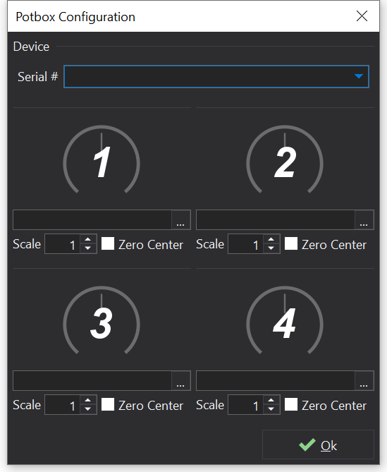
Potbox Configuration
The PotBox configuration dialog is available from the ‘Configure’ menu.
Plug your PotBox into a USB port on the PC. The device should be installed automatically by Windows and does not require any special drivers.
If the device has been correctly detected by the system, you should be able to select it by it’s serial number in the “Serial #” box at the top of the dialog. Once selected, the dials correspond to that PotBox. It is possible to have more than one PotBox attached to your computer at once, should you require more extensive control. Each box can be configured independently.
Configuring one of the rotary encoders
To configure a rotary encoder on the PotBox, ensure that the device is selected and rotate/press the encoder. The corresponding dial should be highlighted on the user interface. To link the encoder to a specific modifier or option, click on the ‘…’ button below the dial and select the object that you wish to control.
The configuration for all devices is stored in the current tabs layout file and is remembered between sessions for specific ECU types.
Scaling
The scale at which the PotBox modifies a value may be configured using the ‘Scale’ and ‘Bipolar’ options.
‘Scale’ is multiplied by the number of detents that the rotary encoder was moved when adjusting the target object.
‘Bipolar’ indicates that the multiplication of ‘Scale’ should take the zero position of the target value into account. i.e. it means that the mid-point of the dial corresponds to zero on the target value.
Link to Controller
The link to controller box makes it possible to link an object such as an option or a modifier channel to either a USB PotBox or a MIDI controller.
Most dials in GWv4 can be linked to a controller my right clicking and selecting ‘Link to Controller’. This includes options in Option Selection Lists and the modifiers on Virtual PotBox windows.
The simplest way to use this with a USB PotBox is to simply press the rotary encoder like a button on the PotBox that you want to use for the linkage and it will be automatically set up.
You can manually set up the various options and may wish to modify the mapping to give a coarser / inverted adjustment by changing the multiplier.
‘Scale’ is multiplied by the number of detents that the rotary encoder was moved when adjusting the target object.
‘Bipolar’ indicates that the multiplication of ‘scale’ should take the zero position of the target value into account i.e. it means that the mid-point of the dial corresponds to zero on the target value.
Calibration Aspects
Calibration Aspects are a way of loading/saving only a portion of a calibration file.
Aspects can be used to store specific aspects of an ECU setup.
For example you might want to save a number of different aspect files that only have the Lambda table and the Lambda In X2 options in them. The resulting files can then be used to quickly reconfigure the ECU based upon a change of lambda sensor.
This is open-ended and can be used to load or save any combination of options, tables and maps.
Aspects can be created from the current calibration by selecting Save Calibration Aspect...
To open a calibration aspect, select Open Calibration Aspect...
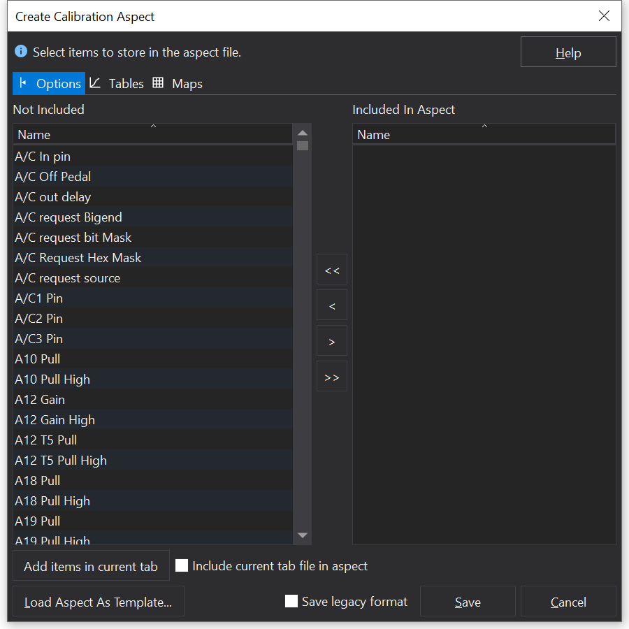
Save Calibration Aspect
Select items that you wish to store in your aspect file in the left hand list and move them to the right hand list.
You can do this using a number of methods:
Double click on an item.
Select items and then drag them across.
Select items and click on the single arrow button.
All items can be moved across using the double arrow button.
To switch between tables, options or maps, click on the appropriate tab at the top of the window.
Once you have selected the items that you want in your aspect file, click on the ‘Save’ button and select a filename for the aspect file.
Load Aspect As Template
You can use a previously created aspect file as a template for generating a new aspect file. This will select all of the same items that were selected in the original file but will use the values that are in the current calibration.
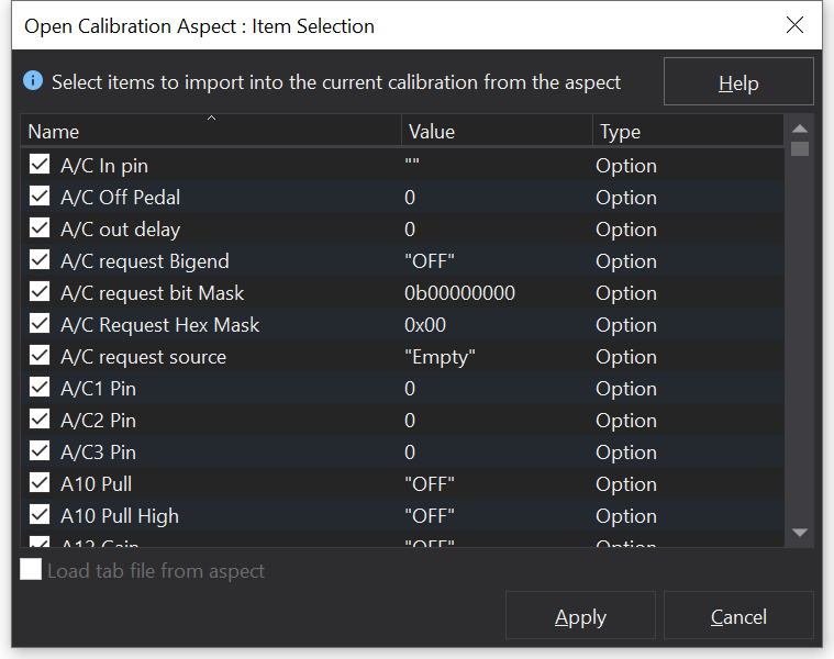
Load Calibration Aspect
This will load the values in a calibration aspect into the current calibration.
Once you have selected the aspect file, you will be offered the opportunity to review the items that will be changed:
If you do not want some of the values to be loaded in, then simply un-tick the items you do not want included
Usually this is unnecessary and you’ll just need to click ‘Apply’.
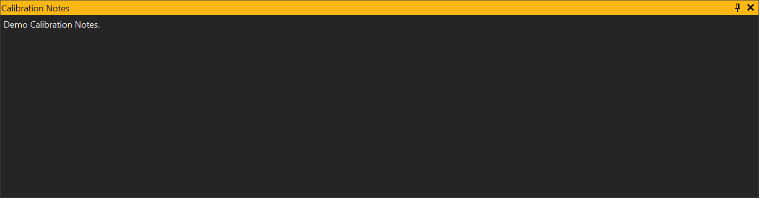
Calibration Notes
The Calibration Notes window is a simple text editor for allowing notes to be saved in the calibration its self. This might be useful when particular changes have been made to the calibration which might need explaining at a later date. To view the Calibration Notes window go to Calibration NotesCtrl-N.
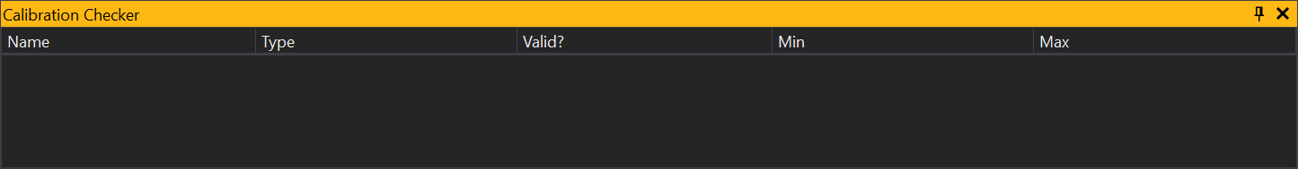
Calibration Checker
To view the Calibration Checker go to Calibration Checker
The Calibration Checker compares all values in the current calibration against limits set by the ECU. If a value is changed to be outside these limits, it will be highlighted in the Calibration Checker window:
The Calibration Checker has the following properties which can be accessed through the context menu (right clicking on the Calibration Checker):
Hide Valid Names - If yes, this will only show values which have invalid values set. If set to no it will show all values in the current calibration.
Popup Invalid - If yes and when the Calibration Checker is hidden, then the Calibration Check will expand to show the invalid values.
 button on the tool bar, or from the main menu select
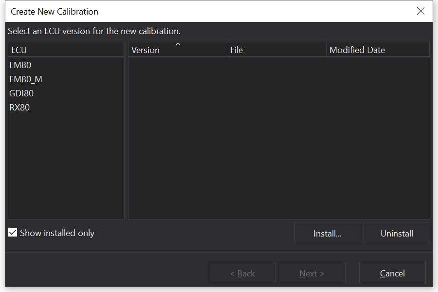
 button. This will undo the last change made. Repeating the process undoes the previous change and so on. If a change affected several sites, for example a percentage change on an area of the Fuel Map, then all the site changes will be done in one process.
 button. In addition to the button illuminating when the calibration is changed, “[modified]” is then displayed in the title bar.
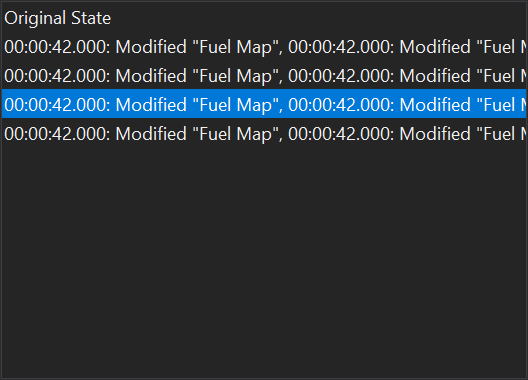
 on the toolbar.
 on the tool bar. Clicking the small down arrow next to this button will display a list of the calibrations which have been opened recently.
 Auto EE
 Error EE Checksum
 ). This will display the following file dialog: