The working area in GWv4, known as the “Workspace” is highly customizable. Different layouts are shown for different types / versions of ECUs and a wide variety of Views for presenting Measurements and Calibration items is provided.
Some views are docked to the edges of the Workspace area and will be shown regardless of which tab is selected.
Docked views can be moved and re-docked via drag & drop. Just press and hold the left mouse button on the title bar of a docked view and drop it onto one of the dock targets that are shown during the drag & drop operation.
Views that are docked to the workspace are available from the following menu commands:
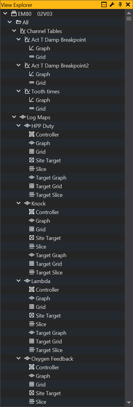
The View Explorer window is a tree view list of all maps, tables, options and channel that are in the current ECU type. The View Selector allows you to select any of these view objects and add them to a tab in your workspace.
The View Selector is made up of a number main folders. These are: Categorised, Profiles, All, and User. These folders all contain the maps, tables channels etc for the current ECU, but group them in different ways.
Categorised: Groups objects by their category i.e. Fuel, ignition, etc.
Profiles: Groups objects by the profile they are in (not available in all products). Profiles are used to distinguish common objects from those that are advanced or for security.
All: Displays all objects, grouped by their type i.e. Maps, tables, options etc.
User: By dragging and dropping objects from other folders the user can create their own structure for storing objects.
Adding an object to the workspace
Adding an object to the workspace using the views selector can be done either by dragging the object into the workspace or by right clicking the object and selecting display. For certain objects there are more than one option as the object can be displayed in more than one way. For example: right clicking on a map will give you the option to display as either a graph or grid.
Splitting the View Explorer
The View Explorer may be vertically split by using the views_split_button button:
This splits the view so that the children of the item selected in the top tree are displayed in the bottom panel. This can make navigating the views tree easier if you expand items with a large number of children.
Properties Window
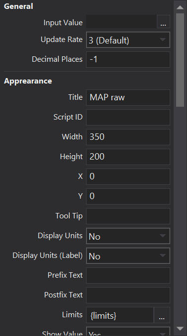
The Properties window displays a list of options and settings for the currently selected object in the workspace. By default it is displayed at the bottom right of the screen but if removed can be re-displayed by selecting it from the menu PropertiesAlt-Enter
Changing properties
The properties window will always display the properties for the last selected object in the workspace. So start by selecting the object in the workspace you want to change. This will fill the properties window with the options for that object. Then simply click on the setting you want to change and type a new value.
Property Description
The property description makes up the bottom part of the properties window. It displays a brief description of the currently selected property. In the picture above a description of the Multiplier property is shown. The description section can also be re-sized by clicking and dragging the line at the top description area.
ECU Status Window
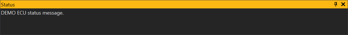
The ECU status window displays the current status of a connected ECU and any messages the occur during the connection process. This could be anything to conformation of a calibration upload to security checks.
By default the ECU status window is displayed at the bottom of the screen, but can be accessed again if removed from the menu ECU Status.
The status window may be suppressed from displaying automatically when connecting by setting the ‘Suppress ECU status popup’ property in the general settings (Preferences...Alt-F7> General) .
Explanation of some messages
Parity error - Is caused by the slight errors in the data received. May occur when ECU is switched off. If some are appearing but the ECU is still connected, it suggests that there is some noise on the communications cable. Either try another cable or move cable away from other electrical equipment. If multiple Parity Errors are being shown and the ECU is not connected, this suggests you connection settings are incorrect.
Framing error - Similar to Parity error.
Error: Rx Timeout - PC has stopped receiving communications from the ECU. Can occur if the ECU is switched off whilst connected.
ECU is not securable - The connected ECU does not have the ability to enable a password on the uploaded calibration.
Comms Monitor
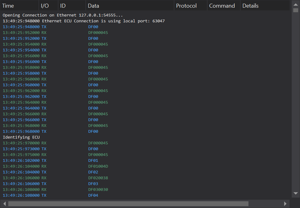
The Comms Monitor Window displays the raw data of the communications between GWv4 and the connected ECU.
Requests from the PC are displayed in blue text and prefaced by a “TX”. Responses from the ECU are displayed in green, and are prefaced by a “RX”.
This can be useful to diagnose some communications problems. The Comms Monitor window is available from the menu: Comms Monitor.
Descriptions
Overview
The descriptions view displays extra details about ECU Objects selected in the GWv4 user interface.
The view may be shown using the action DescriptionsCtrl-D.
Tabs
GWv4 has a ’tabbed’ workspace for placing multiple objects to view and adjust information from the connected unit. Users maybe familiar with this system from other software. Tabs are a way of grouping related view objects into multiple pages that can be switched between. Tabs are displayed at the top of the workspace.
Moving between tabs
Method 1: Simply clicking with the left mouse button on the tab you want to see.
Method 2: Click the button to the right of the tabs. This displays a list of the current tabs from which you can select.
Method 3: Hold down the Ctrl key and press a number on the keyboard that corresponds to the tab you want to view. Notice as in the picture above the first 10 tabs are numbered 1 through to 0.
Method 4: Hold down the Ctrl key and tap the Tab while keeping the Ctrl pressed down. This will bring up the tab navigator. Keep the Ctrl button pressed and use the mouse or arrow keys to select tabs and the items within each tab. The selected view will be displayed when the Ctrl key is released.
Create New Tab
To create a new tab, either select ‘New Tab’ from the Layout menu, or right click on the workspace (which also brings up the layout menu). You will then be asked for a name for the new tab, type the name, click ‘OK’ and the new tab will be created. To rename a tab at any point, just right click on the tab and select ‘Rename Tab’.
Remove Tab
To remove a tab, either; with the tab you want to delete selected click the cross in the top right of the tabs area, or right click on the tab and select ‘Delete Tab’
Re-Order Tabs
The order in which the tabs are displayed can be changed. This can be done by dragging a tab to a new position with the mouse. Press and hold the left mouse button on the tab you want to move.
Saving tabs
To save the current tab as a single tab, select the tab you want to save and from the Layout menu select ‘Save Current Tab’. Type in a name for the saved tab and click ‘OK’. To save all the tabs currently in use, from the Layout menu select ‘Save Tabs’, enter a name and click ‘OK’. This will save all the current tabs as a single file.
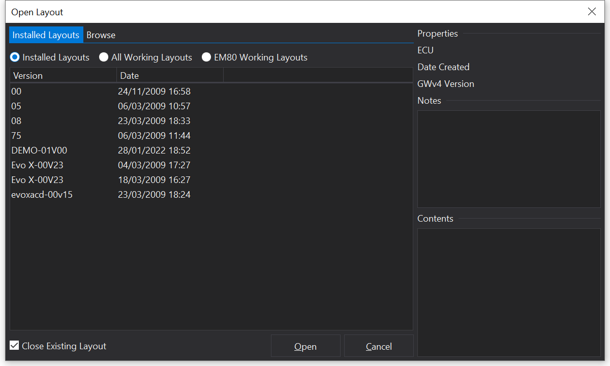
Loading tabs
To load a tab or group of tabs, from the Layout menu select ‘Load Tabs ‘. As file open dialog box will be opened, and you can select some of your previously saved tabs.
There are also some factory tabs provided by GEMS, these can be found by selecting the Factory/Cached Tabs tab at the top left of the file open dialog box. In the Factory/Cached Tabs section you can also view the last tabs used by all ECUs or just the currently attached ECU.
Factory Tabs - These are tab files that are made by GEMS and are installed in GWv4.
Last Viewed: All ECU Types - Will show the last viewed tab layout you were looking at for all ECU types.
Last Viewed: < Current ECU > - This will display the last viewed tab layouts for all versions of the current ECU type.
By default the loaded tabs will replace all the current tabs open. To disable this and load the selected tabs alongside those already open, uncheck the ‘Close Existing Tabs’ in the bottom right.
Reset Tabs
To reset all tabs to a single blank tab, from the Layout menu, select ‘Reset Tabs’.
GWv3 Templates
Templates from GWv3 can be converted into GWv4 tab files. To do this select Import GWv3 Templates... and select the file you want to load. This template will be loaded as a single tab which then can be saved as detailed above.
Configure Shortcut Keys
In GWv4 there are many keyboard shortcuts which can quickly give you access to various options or actions. Keyboard shortcuts can be configured by the user, except for the following which can not be changed.
Fixed Key Commands
Esc - Clear Selection.
F1 - Opens the GWv4 manual.
Ctrl + S - Save calibration.
Ctrl + Z - Undo.
Ctrl + X - Cut.
Ctrl + C - Copy.
Ctrl + V - Paste.
Useful Shortcuts to know
[ ] - The left and right square brackets are used to increase and decrease the value of the current site(s) of a table or map. Holding down the Shift key whilst using these keys will increase or decrease by a larger amount. They can also be used for increasing/decreasing the value in an option list.
These keys were chosen because whilst + and - will work on some views, the program cannot tell if you actually wanted to type in a negative number.
Shift + F10 - Brings up the context menu, same as right clicking on an object.
Ctrl + Tab - Displays the Ctrl+Tab navigator allow quick access to all objects on all tabs.
Alt + Enter - Opens the properties window for the current object.
Page Up / Page Down - These can be used to navigate up and down lists such as, options, channels and the properties window.
Space When online, pressing the Space bar will select the site nearest to the current cursor site in map/table grids.
A full list of keyboard shortcuts can be found here: Shortcut Keys
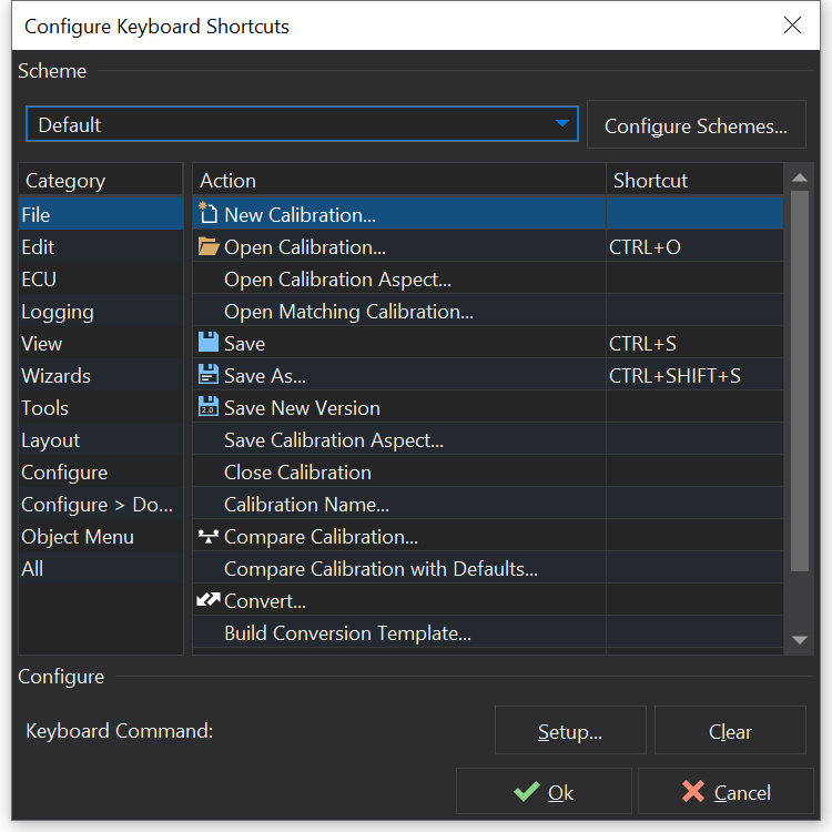
The user can set up or change the remaining keyboard shortcuts. This allows actions that might be used regularly to be assign to a keyboard key or combination of keys. To bring up the shortcut edit from the menu select Keyboard Shortcuts....
Set a new shortcut
Locate the action or menu you would like to set a keyboard shortcut to using the category and Action columns. Make sure the action is selected then click the ‘Setup’ button and simulate the key press you want to use. Once you have clicked OK all your changes will have been implemented.
Schemes
If you want to setup a keyboard set for different scenarios i.e. in-car and workshop, then you can use the action shortcut schemes to setup different sets of keyboard shortcuts for these different scenarios. Click the ‘Configure Schemes’ button. Click ‘Add’, enter a name for the scheme, then click ‘OK’. You can now select this scheme from the Scheme drop down list and edit its keyboard shortcuts.
Colour Scheme (Light/Dark Mode)
Changing the Colour Scheme
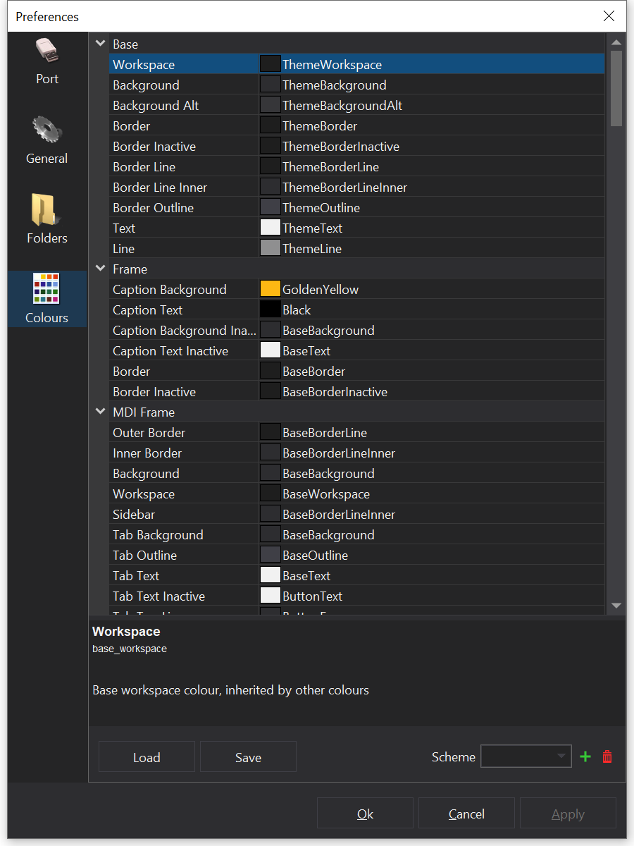
Almost all the colours used in GWv4 can be changed to suit. From the main menu select Preferences...Alt-F7, select the Colours section. This displays list on all the colours used at present.
You load or save your colour selection to a scheme. To load a scheme select one of those installed from the drop-down list at the bottom of the colours section.
To save your current colour settings to an item in this list click the ‘+’ next to the list. To remove an item from the list, select the item, then click the ‘-’ button.
Swapping Between Light and Dark Mode
GWv4 has a light and a dark mode, this is similar to the colour schemes, and each mode does infact have its own colour scheme. Swapping between light and dark mode is just a quick w2ay to change this. To toggle Light/Dark mode simply select Toggle Dark Theme, this will require a restart of GWv4 for the effects to take place.
Setting Default Folders
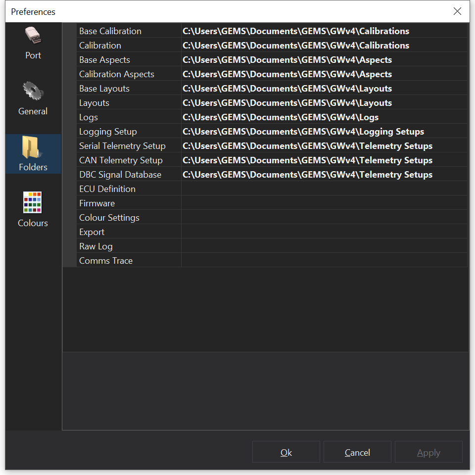
Sets the default access/storing folders for everything GWv4 will use i.e. Calibrations, tabs, firmware etc. This can be accessed by selecting Preferences...Alt-F7 and then selecting the folders tab.
To change the location of a folder click the folder path you want to change then click the ‘…’ button (as above) to select a new folder.
Note
GWv4 manages GIN files for you. The ECU Definition folder listed above is where GWv4 will next look to find a new GIN file to install. GIN files are copied to a special application managed location when installed. Advanced users can override this setting by changing the general preference ‘Install ECU Definitions with Absolute Paths’.
Units
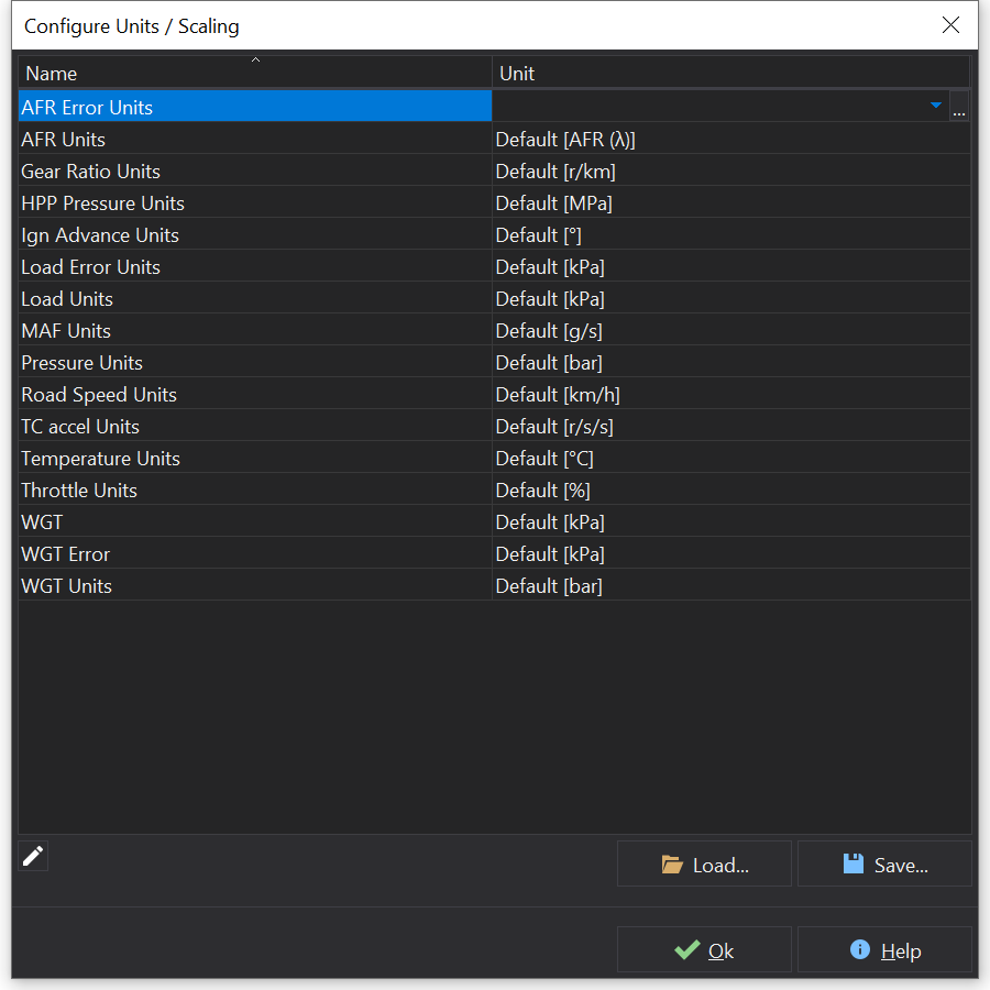
The Units/Scaling Configurator allows you to change the Units that the values of the ECU are displayed in, for example displaying temperature in degrees Fahrenheit instead of Centigrade.
To display the Units/Scaling Configurator from the main menu select Units / Scaling.... The following window will then be displayed:
This window displays a list of all units in the current ECU that are configurable. This may vary between ECUs.
If unit conversions for the given unit can be found, then the drop down box should contain alternative display units.
Click ‘OK’ to apply the changes to the current session. These changes will be remembered by GWv4 for this ECU and version type, so the next time the current ECU type is used the Units settings will be restored.
Loading and Saving settings
The current Unit configuration can be saved and loaded. This can be useful for importing settings between ECUs and versions, or having different setups for working in different countries.
To save the current Unit settings, click ‘Save’, type a name for the settings and click ‘OK’. To load in a saved setting file, click ‘Load’ and select the units settings file you want to load in and click ‘OK’.
Advanced Setup
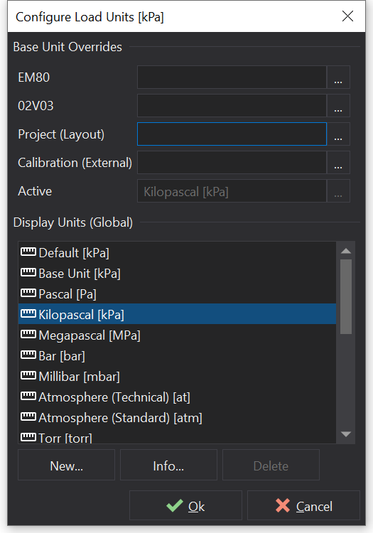
To make more advanced changes to units click on the ‘…’ button of a selected unit. This will sometimes be necessary if you have calibrated a channel using scalar and offset options, or a suitable unit conversion cannot be found, see Unit configuration for more details.
Rescaling of values to display them in different units requires that a base unit can be identified. From this base unit, other units can then be derived for display in GWv4.
In some cases, the unit defined in the GIN (ECU definition) file of older ECU’s is not recognized by the application. In such cases, you can manually set up the intended base unit by selecting it for a specific ECU version or for all ECUs of a given type by setting the appropriate Base Unit Override field.
In other cases this is undesired. Taking MAF Units for the X25 as an example, the value of the “MAF as Load” channel is calibrated using the “MAF Offset” and “MAF Scalar” options in a specific unit. This unit is specific to the calibration file, so setting the base unit override for the calibration file is more appropriate.
Not that such unit selections are not stored in the ECU, so to get them to show up after connecting to and downloading data from an ECU, select “Open Matching Cal When Connected” in the Connection Settings dialog box.
Calibration base units override ECU version specific base units.
ECU version specific units override ECU type specific units.
The active base units based upon these overrides and on those implicitly detected by the application are displayed in the ‘Active’ box.
The display units are derived from the active base unit.
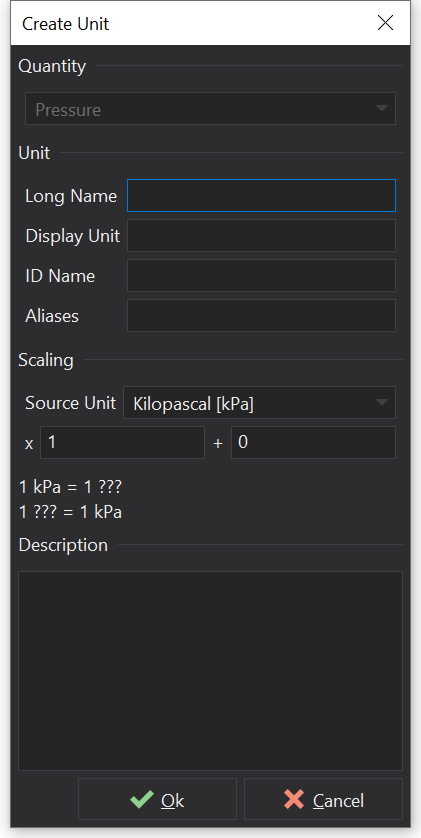
User Defined Units
You can define new units by clicking on the ‘New…’ button:
Fill in the required fields and click ‘Ok’ to create the unit.
The actual unit conversion is set up by entering a multiplier and an offset - currently only simple linear transformations are possible in the form y = mx + c.
The conversion is displayed below as a sanity check that the units are correctly configured.
Currently, new unit quantities are not user definable.
To delete user units, select the unit and click ‘Delete Unit’.
Sizer Based Layouts
Layouts that use sizers can scale better when changing the size of the application window.
Users will have different screen sizes / font sizes / display scaling settings. The set of possibilities has become more diverse in recent times with high pixel density displays (e.g. 4K screens).
Creating Sizer Based Layouts
Drag-select multiple items and select a layout action from the right-click Layout menu. e.g. Layout | Layout Vertically.
If there are no items selected then the layout commands apply to all top-level items on the current page and the layout shall be stretched to fit the whole area.
Editing sizer-based layouts requires the use of the Layout Hierarchy and Properties tool windows.
Use the Layout Hierarchy window to move items into/out of sizers.
Use the Properties window to change the Layout settings (e.g. Preferred Height / Grow Factor).
Style Property Units
Length based ‘Layout’ properties can specify units. These are similar to css e.g., 1dp specifies that a length is 1 ‘density independent pixel’ in size. The actual number of pixels will then depend on the pixel density of the display connected to the computer.
Available Units
Unit
Description
px
Physical pixels.
dp
Density independent pixels. This depends upon the Windows display scaling setting. If display scaling is set to 100% then dp is equivalent to px. However, if display scaling is set to something else such as 150% then 1dp is equivalent to 1.5 physical pixels. Using dp instead of px can make layouts work on a wider range of displays. It may be better to relate view sizes to the selected font size (e.g. ch, em or rem).
ch
Character height for current font. 1ch is equivalent to the height of the current font.
em
’emdash’ character width, relative to the font size of the parent element.
rem
Root emdash - width of the current font on the root work page.
vw
Fraction of the total view width, in percent. 100 being 100% of the view width.
vh
Fraction of the total view height in percent. 100 being 100% of the view height.
vmin
Fraction of the minimum of the view height / width.
vmax
Fraction of the maximum of the view height / width.
%
Percentage of parent container size.
Sizing Algorithm
The sizing algorithm is similar to CSS ‘flexbox’.
Some user interface elements define some defaults for preferred sizes / grow factors. For example buttons prefer to be at their ideal height and not grow or shrink in the Y axis.
 button:
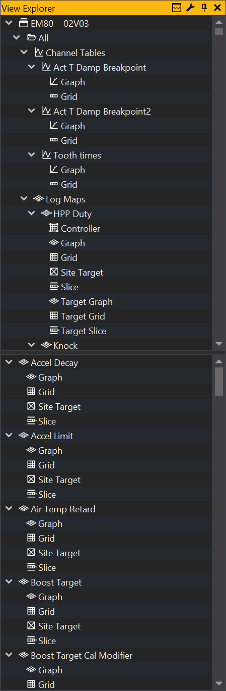
 button to the right of the tabs. This displays a list of the current tabs from which you can select.