Tuning/Setup Guide
Overview
This section of the manual provides a guide to the tuning process using the GEMS software. It is intended to be used as a reference guide for both new and experienced users of the software.
This section of the manual provides a guide to the tuning process using the GEMS software. It is intended to be used as a reference guide for both new and experienced users of the software.
There are a number of concepts / common themes relating to the way that GEMS ECUs function that are useful to understand.
These concepts are described in the following sections:
The ECU contains a number of “objects” that represent settings or measurements and have varying types (e.g. Tables or Maps).
An object in this sense just refers to any ’thing’ in the ECU that can be configured or viewed in GWv4.
Alternatively, an “ECU Object” could be viewed as a memory range in the ECU memory map, which may be a single bit, a byte, a word, or a larger array of items in memory.
This table shows an approximate mapping between the terms used in GWv4 and the terms used in the XCP/A2L and Simulink® worlds.
| GWv4 Term | XCP/A2L Term | Simulink® Term |
|---|---|---|
| Channel Parameter (legacy) |
Measurement | Simulink.Signal (scalar) |
| Option | Characteristic (VALUE) | Simulink.Parameter (scalar) |
| Table | Characteristic (CURVE) | Simulink.Parameter (vector) |
| Map | Characteristic (MAP) | Simulink.Parameter (matrix) |
Note that Options / Tables / Maps are allowed to be stored in non-calibration (i.e. volatile RAM) memory and the same goes for Simulink signals, which is why this mapping is only approximate.
Calibration objects are those that can be modified by the user and are stored permanently by the ECU in non-volatile memory. These values are usually read from the ECU once when connecting to it.
Measurement objects are generally read-only and used to display real-time feedback about the ECU’s operation. Measurements are read frequently from the ECU when visible in the user interface or if they are being used for PC logging. There are some exceptions to this for monitoring some specific ECU functions, such as whether or not there are changes to the calibration that have not been saved to non-volatile memory.
See Calibrations for more information on calibration files / non-volatile storage.
The ECU may be configured to log measurements in internal logging memory for later retrieval. This is useful for diagnosing problems that may not be visible in real-time and offers much more precise timing resolution than is possible when polling the ECU over a comms link.
For many functions, the physical output pins that the function is routed to is user-selectable via ‘Out’ options.
e.g.  Out Oil Feed 1 or Out Oil Feed 1 PWM.
Depending upon the electrical characteristics of the output pin, it may be necessary to invert the output signal.
To invert the sense of the output, use a negative value in the calibration for the output pin.
Some output pins have different features and restrictions. For example, some pins may be used for PWM outputs, digital outputs, or timed.
Care should be taken to ensure that multiple functions are not assigned to the same output pin as this would cause conflicts and un-defined behaviour.
The correct type of pin should be selected for the function being controlled, for example Out Oil Feed 1 PWM must be a PWM-capable output pin.
Refer to the ECU manual for the pin numbering scheme used by the ECU. The internal ECU pin numbering scheme differs to the physical pin numbering on the ECU connector.
Some functions may be configured / linked within the ECU using internal data / channel routing.
For example, the EGT (Exhaust Gas Temperature) sensor may be connected to any input channel, be it a physical analog input or from a CAN message.
Other features are more fixed, such as AIT (Air Intake Temperature) which only allows selection from a list of analog inputs.
Route-able features will typically have a ‘Source’ option that allows the user to select the input channel. The raw value of the input channel is displayed by a corresponding ‘raw’ channel.
For example, the Oil Feed 1 feature has an Oil Feed 1 Source option that selects the input channel for varying the duty cycle. The MSB of the raw input value is displayed by the  Oil Feed 1 raw channel.
Source options often have a ‘Bigend’ option that specifies the upper/lower byte of the input channel, if it is 16bit. This is usually set to OFF. In some cases (e.g. Little Endian data coming via CAN bus) the bytes of the raw input channel may require swapping.
If the Bigend option is OFF then the MSB of the raw input value is displayed by the raw channel.
ECUs will often provide some general purpose ‘User’ tables or maps that can be used for non-linear scaling from abitrary input data.
For example, the  User 1 Duty table can be used to convert a raw input value to a ’tunable’ output value.
These tables and maps can be utilized by using intermediate routing steps.
flowchart LR
    CRX["CAN1 RX1 W1"]-->U1S["User1 Source"]
    U1S-->U1RAW(["User1 raw"])
    U1RAW-->U1DT["User1 Duty Table"]
    U1DT-->U1D(["User1 Duty"])
    U1D-->OF1S["Oil Feed 1 Source"]
Specific CAN messages may be received using the CAN Rx setup (from menu action ) or via CAN RX related options in the calibration.
When the CAN port and CAN RX IDs are configured, the ECU will decompose the CAN message into 4x 16bit channels, e.g. for Message 1 on CAN port 1, the channels are:
CAN1 RX1 W1
CAN1 RX1 W2
CAN1 RX1 W3
CAN1 RX1 W4
If, for example, an external temperature sensor module is used that sends a CAN message to the ECU containing a reading for EGT, then this message could be assigned to a CAN RX message ‘box’ e.g. CAN1 RX1. If the EGT temperature was given in the first 2 bytes then CAN1 RX1 W1 would hold the EGT temperature value, in unscaled form.
To link up CAN1 RX1 W1 to the EGT feature, the EGT Source would be set to CAN1 RX1 W1.
If the received EGT signal is in Little Endian (Intel) format, then the EGT Source Bigend would be set to ON to swap the bytes.
The resulting raw value is displayed by the EGT raw channel and converted to voltage 0…5V for the full-scale input value. This is generally fine for A2D sources but in the case of data received by CAN, this is unlikely to be the correct interpretation. The EGT Sensor table should arrange to convert from these pseudo-volts to valid temperature.
For this example, the temperature module reports temperatures as signed 16bit numbers with 0.1°C resolution per bit. This poses a problem since EGT raw is unsigned and there is no way to make the source be interpreted as a signed number directly.
The EGT Sensor table would need to convert the signed number to an unsigned one by having a discontinuity. Note that hexadecimal values can be directly entered into the table cells (including the axis for many tables, like EGT Sensor).
This table shows the conversion from the EGT raw channel to a temperature in °C. Notice the discontinuity at 0x8000, which is the point where the signed number changes from full-scale positive to full-scale negative:
| EGT raw (hex) | EGT raw (V) | Temperature °C |
|---|---|---|
| 0x0000 | 0.0 | 0 |
| 0x7FFF | 2.49996 | 3276.7 |
| 0x8000 | 2.50004 | -3276.8 |
| 0xFFFF | 5.00 | -0.1 |
However, the EGT Sensor only supports positive output values, from 0 to 1275°C, depending on the value of the Temp Scalar option. See User Scalars for more details on the purpose / effect of scaling factors like Temp Scalar.
If there are 8 cells in the EGT Sensor table, the following values could be used, assuming that the Temp Scalar option = 1 (or 0, in which case the scalar is ignored) and that GWv4 is configured to display temperatures in units of degrees:
| EGT raw (hex) | EGT raw (V) | Temperature °C |
|---|---|---|
| 0x0000 | 0.0 | 0 |
| 0x31CE | 0.97276 | 1275.0 (max) |
| 0x7FFF | 2.49996 | 1275.0 |
| 0x8000 | 2.50004 | 0 (min) |
| 0xFFFF | 5.00 | 0 |
| 0xFFFF | 5.00 | 0 |
| 0xFFFF | 5.00 | 0 |
| 0xFFFF | 5.00 | 0 |
The axis breakpoints table values should be sorted in increasing order for the ECU to be able to interpolate correctly. In this example, not all the table sites are used; so the remainder of the table is filled with the same values as the last useful row to maintain ordering.
For ECUs that use a Simulink® model, CAN signals may be decoded from a DBC file. The messages are defined ahead of time as part of the firmware build process, the channels in the DBC file become available for use in the Simulink model as Simulink signals.
User Scalars are a feature that allows the units of values to be changed. ‘Option User Scalars’ also reference calibration options for to apply configurable scaling factors.
Scaling options e.g. like Temp Scalar are stored by the ECU but are not directly involved in any of the ECU’s internal calculations.
Internally the ECU works with (typically) raw integer or ‘fixed point’ integer values (variables), and less commonly with floating point values. ECUs running Simulink® models are more likely to be using floating point numbers internally.
As far as the ECU is concerned, any quantities (temperatures, pressures, speeds, oxygen concentrations etc) are just numbers and the units are generally not important. The relationship between values, however, is important and additionally that related quantities use the same internal scaling.
Since integers are discrete values, there is a limit to how precisely values can be represented. The ECU may be able to offer more precise control if important quantities are scaled to make the best possible use of the available range of variables that represent them.
Consider an ECU table that contains 8 bit values; there are only 256 possible states / steps in each cell of the table. If the maximum expected range of physical values can be mapped to fit onto this 0…255 range, then the ECU can make the most precise control decisions. The scaling options, therefore, are telling GWv4 how to convert from these internal raw values into physical units. In other words, the ECU is using a custom type of units and the scaling options are defining how those custom units correspond to a physical ‘real-world’ unit.
For example, Temp Scalar is used as a scaling factor for a number of temperature values in the GWv4 user interface. The scaling is purely for display purposes - but it can mean that higher resolution temperature values can be used internally by the ECU. The units may also be further converted from °C by GWv4 to a different unit (e.g. °F) for display purposes - see Unit configuration.
Internally, the ECU does not care what the units are, just that values represent ratios for control purposes. Changing the units displayed in GWv4 does not change the internal operation of the ECU whatsoever.
Many tables and maps are preconfigured with sensible scaling factors and may not offer the ability to change them, where the level of precision is not so critical or where the range of input values is predictable.
If an item is scaled using an Option User Scalar, this will be apparent in the Descriptions View. There may be a ‘Scalar’ (multiplier) option and/or an ‘Offset’ (signed addition) option.
For example, the Engine Load channel is scaled using the Load Scalar and Load Offset options.
These same scaling factors are used anywhere that raw Engine Load channel values might be encountered so that GWv4 will display them all correctly and the ECU can compare them consistently.
For example, the  Fuel map might use the Engine Load channel as the input to one of its axes, and the RPM channel as the other axis. The load axis breakpoints may be configured, giving a non-linear axis to give more precise control at some points in the engine’s operating range.
The ECU will compare raw Engine Load values to the (raw) breakpoints in the Fuel map, and interpolate between them to find the correct fueling value. The ECU does not care what the actual units are - it is only operating on the raw integer values that represent the engine load. The GWv4 software will use the Load Scalar and Load Offset options so that the load values can be presented on screen in meaningful units.
The ECU has a number of inputs - typically analog, digital and message busses (e.g. CAN) that provide it feedback about the system under control.
The ECU has a number of Analog to Digital Converter (ADC) inputs that can be used to measure analog signals. These inputs may be assigned to different functions by setting options in the calibration.
Some channels have software selectable pull-up or pull-down resistors. These can be used to bias the input voltage to a known level when the input is not connected. This can be useful for sensors that do not have a built-in pull-up or pull-down resistor.
There are typically 2 options to control the pull-up or pull-down resistor. For example, the following table shows the options for Analog 10:
| A10 Pull |
T1 Pull High |
Description |
|---|---|---|
| Off | Off | No pull-up or pull-down resistor (floating) |
| Off | On | No pull-up or pull-down resistor (floating) |
| On | Off | Pull-down resistor enabled |
| On | On | Pull-up resistor enabled |
Some of the timing inputs have a pull-up resistor that can be enabled or disabled. Often the timing input would also have a fixed higher value pull-down resistor.
For example, the following table shows the options for T1 on a typical ECU:
| T1 Pull-up |
Description |
|---|---|
| Off | 10k Pull-Down (used with VR sensor) |
| On | 1k Pull-Up (used with Hall sensor) |
Input from various sources can be used to generate digital ‘switch’ (on/off) channels by a variety of methods. These internal switch channels may be selected numerically to control various functions in the calibration.
Some switches may be configured to come from external sources, such as CAN messages or digital input pins.
Switch A.
Switches selected from user source (e.g. CAN).
Attached to the ECU are a number of sensors that provide information about its environment (e.g. feedback from an engine).
These sensors are connected to the ECU through the wiring loom and provide data that is used to control the engine.
Some sensors have special processing in the ECU to convert their raw data into a more useful form. For example, a temperature sensor may provide a raw voltage that is converted into a temperature reading.
The Engine Load may be measured in a variety of ways, such as using a Manifold Absolute Pressure (MAP) sensor (Boost Pressure), a Mass Air Flow (MAF) sensor, or a Throttle Position Sensor (TPS). Pedal position may also be used.
MAP or MAF may use Pedal as a backup should the primary sensor fail.
The Load Scalar is used to convert the raw ’load’ values into more meaningful physical units.
If Fuel Map Pedal is On, then a correction, Boost Correction from the Boost Correct table is used to correct for the change in air pressure entering the engine.
This can result in a more responsive Pedal.
Note the Fuel Pedal map is used instead of Fuel map as the base fuelling in this case.
The Mass Air Flow (MAF) sensor measures the mass of air entering the engine. This may optionally be used to calculate the amount of fuel required to maintain the desired air/fuel ratio.
The MAF sensor is typically a hot wire or hot film sensor, which heats a wire or film to a constant temperature and measures the cooling effect of the air flow. The cooling effect is proportional to the mass of air flowing past the sensor.
The voltage output of the MAF sensor is often non-linear, so the ECU may apply a calibration curve to convert the raw voltage into a more useful linearized form.
| Option | Description |
|---|---|
| MAF |
Use MAF as the “Engine Load” measurement? |
| MAP |
Set to 0 if using MAF for Engine Load. |
| Load source |
Do not set if using MAF for Engine Load. |
| MAF source |
Select an input channel to use for MAF. This could be an Analogue input or another source such as CAN bus. |
| MAF source Bigend |
Swaps the bytes from the 16bit MAF source. This may be required if the source is from a little-endian (Intel) 16bit CAN signal. |
| MAF Raw |
Raw MAF sensor reading as obtained from the MAF source. |
| MAF no Speed comp |
If ON, the MAF sensor reading is not compensated for engine speed. Otherwise, the MAF sensor reading is multiplied by the inverse engine speed and divided down. |
| MAF no X16 |
If ON, the MAF sensor reading is not multiplied by 16, following speed compensation. This option does nothing if MAF no Speed comp is ON. |
| MAF Sensor |
MAF Sensor Table to convert raw MAF sensor voltage into a linearized form. |
| MAF Cal |
Number of internal teeth over which to average the MAF sensor readings when running. Typically this would be set to 1, 2 or 3 revolutions; the actual value to set here would depend upon the number of internal teeth per revolution which should be configured in the Wheel Teeth option. |
| MAF min |
Minimum MAF sensor reading, below which an error condition is indicated. |
| MAF max |
Maximum MAF sensor reading, above which an error condition is indicated. |
| MAF Linear |
Linearized MAF reading, scaled using MAF (Load) Scalar. |
| MAF Linear Scaled |
Linearized MAF reading, scaled using MAF Scalar. |
| MAF as Load |
Compensated MAF reading, scaled using MAF (Load) Scalar. |
| MAF as Load Scaled |
Compensated MAF reading, scaled using MAF Scalar. |
| Error MAF |
Indicates an error condition with the MAF sensor. |
flowchart TD
    MAFMIN@{ shape: diamond, label: "< MAF Min"}

    MAFMAX@{ shape: diamond, label: "> MAF Max"}
    MAFNSPD@{ shape: diamond, label: "MAF no Speed comp"}
    NOMAFMUL@{ shape: diamond, label: "MAF no X16"}

    MAFRAW["MAF Raw"]

    MAF_Source(["MAF source"])-- RUNNING? -->MAFSMP(["MAF samples"])
    MAFSMP-->MAFAVG["Average"]-->MAFRAW
    MAFCAL(["MAF Cal [teeth]"])--"Window Size"-->MAFAVG
    MAF_Source--"NOT RUNNING"-->MAFRAW

    MAFRAW-->MAFMIN
    MAFMIN-- Y -->ERROR_MAF(["Error MAF"])
    MAFMIN-- N -->MAFMAX

    MAFMAX-- Y -->ERROR_MAF(["Error MAF"])
    MAFMAX-- N -->MAFTBLW["MAF Sensor Table"]
    SPEEDN(["− Engine Speed"])
    MAFTBLW-->MAFLIN(["MAF Linear [MAF Load Units]"])
    MAFLIN-->MAFLINSCALED(["MAF Linear Scaled [MAF Units]"])


    MAFLIN-->MAFNSPD
    MAFNSPD-- N -->SPEEDMUL["×"]
    MAFNSPD-- Y -->MAFLOAD
    SPEEDN-->SPEEDMUL

    SPEEDMUL-->NOMAFMUL

    NOMAFMUL-- N -->MUL16["×16"]
    NOMAFMUL-- Y -->MAFLOAD
    MUL16--> Overflow -->ERROR_MAF
    MUL16-->MAFLOAD

    MAFLOAD(["MAF as Load [MAF (Load)]"])

    MAFLOAD-- "MAF AND NOT MAP AND NOT "Load Source"" -->LOAD(["Engine Load [Load]"])
    MAFLOAD-->MAFLOAD_SCALED(["MAF as Load Scaled [MAF Units]"])
MAP sensors measure the pressure of air entering an engine (Manifold Absolute Pressure). This information may be used by the ECU to calculate the amount of fuel required for combustion.
There are typically two MAP sensor inputs on the ECU, with the two sensors being used for redundancy and error checking.
The voltage output of the MAP sensor is typically linear with pressure, and the ECU can be configured to convert this voltage into a pressure reading in kPa.
The MAP sensor can optionally be used as a measure of Engine Load, in which case the ECU will convert the pressure reading into a load value. This load value is used as an axis input for many of the ECU’s calibration tables such as the Fuel map or the Ignition map.
| Option / Channel | Description |
|---|---|
| MAP |
Use MAP as the “Engine Load” measurement? |
| MAF |
Set to 0 if using MAP for Engine Load. |
| Load source |
Do not set if using MAP for Engine Load. |
| MAP Source |
The source of the MAP sensor data. This is an analog input number. |
| MAP2 Source |
The source of the 2nd MAP sensor data. This is an analog input number. If using a single MAP sensor, MAP2 Source should be set to the same value as MAP Source |
| MAP Cal |
Number of internal teeth over which to average the MAP sensor readings when running. Typically this would be set to 1, 2 or 3 revolutions; the actual value to set here would depend upon the number of internal teeth per revolution which should be configured in the Wheel Teeth option. |
| MAP1 samples |
When running this table is filled with the samples used for averaging MAP1. |
| MAP2 samples |
When running this table is filled with the samples used for averaging MAP2. |
| MAP raw Invert |
Inverts the MAP sensor reading, useful for some sensors that output a voltage that decreases with pressure. This same setting applies to both MAP sensor inputs. |
| MAP1 raw |
Result of averaging / inverting the MAP sensor voltage readings. This value can be monitored to verify the MAP sensor input configuration and that the analogue input is reading the MAP sensor correctly. |
| MAP2 raw |
Result of averaging / inverting the second MAP sensor voltage readings. This value can be monitored to verify the MAP sensor input configuration and that the analogue input is reading the MAP sensor correctly. |
| MAP Min Error |
The minimum valid voltage for the MAP sensor. If MAP raw reads below this value, an error will be triggered Error MAP.If MAP2 raw reads below this value, an error will be triggered Error MAP2. |
| MAP Max Error |
The maximum valid voltage for the MAP sensor. If MAP raw reads above this value, an error will be triggered Error MAP.If MAP2 raw reads above this value, an error will be triggered Error MAP2. |
| MAP ref low Volts |
The voltage output of the MAP sensor at a low pressure reference value MAP ref low Pressure. |
| MAP ref low Pressure |
The physical pressure reading from the MAP sensor when the voltage reading from the analogue input reads MAP ref low Volts. |
| MAP ref high Volts |
The voltage output of the MAP sensor at a high pressure reference value MAP ref high Pressure. |
| MAP ref high Pressure |
The physical pressure reading from the MAP sensor when the voltage reading from the analogue input reads MAP ref high Volts. |
| MAP Pressure Max |
If non-zero, this overrides the calculated MAP for Load Max for re-scaling MAP. |
| MAPM |
The MAP sensor calibration multiplier, derived from the reference low and high pressure and voltage values. |
| MAPC |
The MAP sensor calibration constant, derived from the reference low and high pressure and voltage values. |
| MAP for Load Max |
Indicates the maximum pressure that the MAP sensor can read. This value is used to scale the MAP sensor readings to a load value. |
| MAP for Load Scalar |
Alias of MAP for Load Max |
| MAP1 abs |
The absolute value of the MAP sensor reading, in kPa. |
| MAP1 abs FP |
The absolute value of the MAP sensor reading, scaled using Fuel Pressure Scalar. |
| MAP2 abs |
The absolute value of the second MAP sensor reading, in kPa. |
| MAP2 abs FP |
The absolute value of the second MAP sensor reading, scaled using Fuel Pressure Scalar. |
| MAP abs Peak |
Maximum of MAP1 abs or MAP2 abs, in kPa. |
| MAP abs Peak FP |
Maximum of MAP1 abs or MAP2 abs, scaled using Fuel Pressure Scalar. |
| MAP1 as Load |
MAP abs is rescaled by the ECU to make more use of the full-scale range. Scaled to physical units using Load Scalar. |
| MAP2 as Load |
MAP2 abs is rescaled by the ECU to make more use of the full-scale range. Scaled to physical units using Load Scalar. |
| MAP1-MAP2 |
The difference between MAP1 as Load and MAP2 as Load. |
| MAP1+MAP2/2 |
The average of MAP1 as Load and MAP2 as Load. |
| MAP as Load |
The average of MAP1 as Load and MAP2 as Load, unless an error is detected (e.g. out of range voltage) in either input, in which case the valid input value is used where possible. |
| Engine Load |
If the ECU is configured to use MAP as the measurement of Engine Load, this channel will show the value of MAP as Load. This value is scaled to physical units using Load Scalar, as with MAP as Load. |
| Error MAP |
Error flag for MAP sensor 1. Set if the voltage reading is outside the range defined by MAP Min Error and MAP Max Error. |
| Error MAP2 |
Error flag for MAP sensor 2. Set if the voltage reading is outside the range defined by MAP Min Error and MAP Max Error. |
| Barometer |
The barometric pressure reading, in kPa. |
| Boost1 gauge |
The difference between MAP1 abs and Barometer, in kPa. |
The MAP1 abs value is rescaled to make full use of the range. This may therefore require adjustment to the Load Scalar to arrive at correct pressure values for MAP as Load and Engine Load.
Be aware that if the MAP sensor is not being used as a measure of Engine Load then the Load Scalar could be in use by something else. For example, if Load source is being used for Engine Load then the Load scalar may be responsible for rescaling the data selected by Load source so that Engine Load is in the correct units.
flowchart TD
    MAPMINER@{ shape: diamond, label: "< MAP Min Error"}

    MAPMAXER@{ shape: diamond, label: "> MAP Max Error"}
    MLDMAX_D@{ shape: diamond, label: "> MAP for Load max"}

    BARSCLD(["Barometer"])
    MAP1_abs(["MAP1 abs"])

    MAP_Source(["MAP Source (A2D)"])-- RUNNING? -->MAP1SMP(["MAP1  samples"])
    MAP1SMP-->MAP1AVG["Average"]-->MAP_raw_Invert
    MAPCAL(["MAP Cal [teeth]"])--"Window Size"-->MAP1AVG
    MAP_Source--"NOT RUNNING"-->MAP_raw_Invert["MAP raw Invert?"]
    MAP_raw_Invert-->MAPRAW1(["MAP1 raw [V]"])
    MAPRAW1-->MAPMINER
    MAPMINER-- Y -->ERROR_MAP(["Error MAP"])
    MAPMINER-- Y -->MAP_ZERO["0"]-->MAP1_abs(["MAP1 abs"])

    MAPMINER-- N -->MAPMAXER

    MAPMAXER-- Y -->ERROR_MAP(["Error MAP"])
    MAPMAXER-- Y -->MAP_FULL["MAX"]-->MAP1_abs(["MAP1 abs"])
    MAPMAXER-- N -->MAP1M["×"]
    MAPM-->MAP1M
    MAP1M-->MAP1C["+"]
    MAPC-->MAP1C
    MAP1C-->MAP1_abs

    MAP1M_SRC["(MAP ref high Pressure − MAP ref low Pressure) / (MAP ref high Volts − MAP ref low Volts)"]
    MAP1M_SRC-->MAPM(["MAPM"])

    MAP_Ref_low_v["MAP ref low Volts"]-->MAPC_M["×"]
    MAPM-->MAPC_M

    MAP_Ref_low_p["MAP ref low Pressure"]-->MAPC_C["−"]
    MAPC_M-->MAPC_C
    MAPC_C-->MAPC(["MAPC"])

    MAPC-->MLDMAX_ADD["+"]
    MAPM-->MLDMAX_ADD["+"]
    MLDMAX_ADD-->MLDMAX(["MAP for Load Max [kPa]"])
    MLDMAX_ADD-->MLDS(["MAP for Load Scalar"])

    MLDMAX-->MLDMAX_D
    MLDMAX-->MAP1_abs_DIV

    BARSCLD-->MAP1_abs_sub
    MAP1_abs-->MAP1_abs_sub["−"]

    MAP1_abs_sub-->BSTGAGE1["Boost1 gauge"]

    MAP1_abs-->MLDMAX_D
    MLDMAX_D-- Y -->MAP1_abs_FULL["MAX"]-->MAPLOAD1(["MAP1 as Load [Load]"])
    MLDMAX_D-- N -->MAP1_abs_DIV["/ MAP for Load max"]-->MAPLOAD1(["MAP1 as Load [Load]"])

    MAPLOAD1-->MAPLOAD1_MINUS_2
    MAPLOAD2(["MAP2 as Load [Load]"])-->MAPLOAD1_MINUS_2

    MAPLOAD1_MINUS_2["−"]-->MAPLDIFF(["MAP1-MAP2 [Load]"])

    MAPLOAD1-->MAPLOAD1_AVG_2
    MAPLOAD2-->MAPLOAD1_AVG_2
    MAPLOAD1_AVG_2["Average OR Select"]-->MAPLDAV(["MAP1+MAP2/2 [Load]"])
    MAPLOAD1_AVG_2-->MAPLOAD(["MAP as Load [Load]"])

    MAPLOAD-- "MAP AND NOT MAF AND NOT "Load Source"" -->LOAD(["Engine Load [Load]"])
The ECU has a number of electrical outputs that can be used to control various devices through the wiring loom. These outputs may be assigned to different functions by setting options in the calibration.
Outputs are typically either PWM or digital outputs. PWM outputs are used to control devices that require a proportional control signal, such as a valve or a motor. Digital outputs are used for devices that require a simple on/off control signal.
See also Output Pins.
Oil Feed outputs may also be repurposed and used as slow pulse width modulated (PWM) outputs, or low resolution user signals.
The ECU has a number of digital outputs (ON / OFF) that can be used to control various devices through the wiring loom. These outputs may be assigned to different functions by setting options in the calibration.
Some digital outputs may be switched to other functions such as PWM or timed outputs. For devices that require a proportional control signal, use a PWM output channel instead.
The ECU has a number of Pulse Width Modulated (PWM) outputs that can be used to control various devices. These outputs may be assigned to different functions such as VV control, Idle valve, Wastegate, Servo.
Some PWM outputs may be claimed by specific functions. For instance, if Active Throttle is enabled, it owns a bridge driver and prevents others attempting to use the output, unless e.g. Act T 1 No Drive is set to ON.
Some PWM channels have usage / precision restrictions - see the specific PWM channel documentation for details.
The duty cycle of a PWM signal is the ratio of the ‘on’ time to the total period of the signal. The frequency of the PWM signal is the rate at which the signal repeats. Over time, this produces a proportional control signal with low power loss.
For devices that require a simple on/off control signal, use a digital output channel instead.
PWM outputs must be enabled using options in the calibration and are typically routed to from ECU functions using additional calibration options.
Some PWM outputs are used for specific features such as active throttle, so some care is required to avoid conflicts.
PWM1-16 are fixed to individual pins, however, PWM17 onwards are assignable to any simple output pin. In the pin-outs diagram/table, these fixed PWMs have a code of ‘Pnn’, where ‘nn’ is 01-16.
For PWMs that may be assigned to output pins, pin assignment options are available in the calibration.
e.g.
Out PWM17
As with any other output pin assignment, using a negative value will invert the output signal.
Note that output pin assignments differ to PWM numbers. For example, Out PWM17 is a pin number. Out Oil Feed 1 PWM is a PWM number (which may be further routed to a pin).
See Oil Feed Outputs for details on the Oil Feed channels - which can either use PWM outputs or generate low-speed PWMs in software on simple digital outputs.
Timed output pins are used for precisely timed pulses for functions such as Ignition, Injection, High Pressure Pump, etc.
On the EM80, there 8 x 8bit PWM output pins that can be PWM outputs 1 to 8, injector outputs 1 to 8 or simple low-side outputs.
Timed outputs allow the processor to schedule asynchronous events like ignition in response to crank tooth interrupts, with high precision timing and are enable features like variable ignition advance / retard to work.
GEMS ECUs typically provide 4 Oil Feed output controllers for controlling solenoid pumps. This section discusses Oil Feed 1, but the same principles apply to the other Oil Feed output controllers.
Oil Feed outputs may also be repurposed and used as slow pulse width modulated (PWM) outputs, or low resolution user signals.
It is recommended that the behaviour of the oil outputs is tested following configuration. Monitoring the associated output pin channel using a Scope View or a physical oscilloscope is recommended.
Each oil feed controller has a set of configuration options. Considering Oil Feed 1:
| Option | Description |
|---|---|
| Oil Feed 1 Source |
Selects an input channel for varying the duty cycle. The MSB of the raw input value is displayed by the Oil Feed 1 raw channel. |
| Oil Feed 1 Source Bigend |
Specifies upper/lower byte of the input channel, if it is 16bit. This is usually set to OFF. In some cases (e.g. Little Endian data coming via CAN bus) the bytes of the raw input channel may require swapping. |
| Oil Feed 1 Mul |
Multiplier for re-scaling the raw input value, saturates at 100% duty cycle in case of overflow. The result is stored in Oil Feed 1 Duty |
| Oil Feed 1 PWM OutOut Oil Feed 1 PWM |
PWM channel number for high rate / precision PWM, using PWM output settings with duty cycle Oil Feed 1 Duty. Note: PWM numbers are not the same as output pin numbers. |
| Oil Feed 1 OutOut Oil Feed 1 |
Digital output pin for low rate PWM, only used if Oil Feed 1 PWM Out = 0. If a negative value is supplied for the pin number here (e.g. ‘-5’), the signal is inverted (on e.g. pin ‘5’). In this case there are additional Oil Feed options to control the software PWM. |
Changing the output pin (Oil Feed 1 PWM Out or Oil Feed 1 Out) may leave the prior output in an undefined state. It is recommended to store the calibration and power-cycle the ECU following output pin changes.
If the Oil Feed output is using a digital output instead of a PWM output, a low frequency / low precision PWM is generated by software.
The following common options are effective in this mode:
| Option | Description |
|---|---|
| Oil Feed 1 Stop Duty |
If ON then when Stat Running is OFF, Oil Feed 1 Duty Stopped will be used for the duty cycle of the output, unless Oil Feed 1 Stopped OFF is ON (in which case the output would be switched ‘OFF’). |
| Oil Feed 1 Duty Stopped |
Duty cycle to use when engine is not running (Stat Running is OFF), depending upon Oil Feed 1 Stop Duty and Oil Feed 1 Stopped OFF options |
| Oil Feed 1 Fixed On |
Use a fixed-length ON pulse, with the duty cycle affecting the duration of the space between ON pulses. |
| Oil Feed 1 Stopped OFF |
If ON then the output will be switched off when the engine is not running (Stat Running is OFF), otherwise the output will be set to Oil Feed 1 Duty Stopped. |
Enabled when Oil Feed 1 Fixed On = ON.
This mode uses a fixed duration ON pulse and variable duration OFF interval.
| Option | Description |
|---|---|
| Oil Feed 1 Fixed On |
ON |
| Oil Feed 1 Fixed T.B. |
Maximum duration of variable part of OFF period, in milliseconds (added to Oil Feed 1 OFF min). |
| Oil Feed 1 Fixed comp |
If set, changes the type of complement operation performed on Oil Feed 1 Duty prior to scaling Oil Feed 1 Fixed T.B.. If ON then a 1’s complement (logical NOT) is used instead of 2’s complement (arithmetic negation). It is recommended to set this to ON for new calibrations and can give better results at higher frequencies. |
| Oil Feed 1 OFF min |
Minimum duration of OFF period, in milliseconds. |
| Oil Feed 1 Fixed ON Duty |
Fixed duration of ON pulse, in milliseconds. |
| Oil Feed 1 Period |
Reports current period of signal. |
| Oil Feed 1 T Count |
Count-up timer, used for signal generation. |
The duration of the ‘OFF’ interval is calculated by scaling option Oil Feed 1 Fixed T.B. by the (inverted) duty cycle percentage shown by Oil Feed 1 Duty.
The OFF interval can’t ever be 0 and will have a lower limit of 1ms. The lower limit may be clamped to a higher value by setting the Oil Feed 1 OFF min option.
Oil Feed 1 Fixed ON Duty option defines the duration of the ON pulse. This added to the calculated OFF duration to give the total period of the PWM signal and is placed in Oil Feed 1 Period.
Oil Feed 1 T Count counts up every millisecond.
When Oil Feed 1 T Count exceeds the value of Oil Feed 1 Period, the output is switched on and Oil Feed 1 T Count is reset to 0.
When Oil Feed 1 T Count reaches Oil Feed 1 Fixed ON Duty, the output is switched off.
Enabled when Oil Feed 1 Fixed On = OFF.
Proportional mode has a fixed period and varies the duty cycle of the signal over that period. Additionally this mode can limit the total number of pulses delivered to the output after ECU reset.
| Option | Description |
|---|---|
| Oil Feed 1 Fixed On |
OFF |
| Oil Feed 1 Duty Max |
Maximum ON period |
| Oil Feed 1 Fixed comp |
If set, changes the type of complement operation performed on Oil Feed 1 Duty prior to scaling Oil Feed 1 Duty Max. If ON then a 1’s complement (logical NOT) is used instead of 2’s complement (arithmetic negation). It is recommended to set this to ON for new calibrations and can give better results at higher frequencies. |
| Oil Feed 1 Time base |
Total period of the PWM signal, in milliseconds. |
| Oil Feed 1 P Max |
Maximum number of pulses to deliver to the output before ECU reset. If 0, then no limit is applied. |
| Oil Feed 1 P Count |
Reports the number of pulses delivered to the output when Oil Feed 1 P Max is non-zero. |
| Oil Feed 1 Duty Time |
Stores the result of scaling Oil Feed 1 Duty Max by Oil Feed 1 Duty. |
| Oil Feed 1 T Count |
Count-down timer, used for signal generation. |
New calibrations may prefer to use Oil Feed 1 Fixed On = ON.
In Proportional Mode, some ECUs will have an initial 65 second delay before the output PWM becomes operational.
Low values in Oil Feed 1 Duty result in higher duty cycles (effectively inverted).
Oil Feed 1 T Count is decremented every millisecond. When Oil Feed 1 T Count reaches zero, the output is switched off.
When the output is switched off, Oil Feed 1 T Count is reset to Oil Feed 1 Time base. Additionally the result of scaling Oil Feed 1 Duty Max by Oil Feed 1 Duty is stored in Oil Feed 1 Duty Time. Note that this does not happen in ‘Fixed Mode’.
When Oil Feed 1 T Count reaches the value of Oil Feed 1 Duty Time, the output is switched ON.
When switching on the output, if Oil Feed 1 P Max option is non-zero then the Oil Feed 1 P Count will count up to this value, and the output will cease to be switched on again until the ECU is reset when Oil Feed 1 P Max pulses have been delivered to the output.
Oil Feed 1 Duty Max should be less than or equal to Oil Feed 1 Time base. The sense of Oil Feed 1 Duty is inverted, so that a value of 0 is really 100% duty cycle. This can be inverted by setting a negative output pin number in Oil Feed 1 Out.
The ECU provides user tables and maps that may be used to control the Oil Feed outputs.
See ECU Internal Routing for details on how to route these user maps to the Oil Feed outputs.
Some GEMS ECUs provide dedicated on-board “Peak & Hold” injector outputs that provide a specially shaped pulse to drive injector solenoids.
Fuel Injector settings need either the manufacturer’s data (often restricted) or flow bench test results. GEMS may be able to provide Calibration Aspect files for specific injectors or the layout may include selectors for common injector types.
Instead of a simple ON/OFF signal driving an injector solenoid, the drive transistor is first driven hard on for a specified time to ensure opening, then the current is dropped to a holding current, minimising heat dissipation in both injector and transistor. When the injector is closed, the driver circuit recirculates energy from the collapsing magnetic field of the injector coil, preventing abrupt closure of the injector which can lead to physical injector damage (fuel leakage) and unpredictable fuel delivery due to pintle bounce.
The peak & hold injectors are active if Injector Peak & Hold = ON.
Note if injector outputs 4 to 8 are not used as injectors their recirculation diodes may be turned on, to reduce currents when used as PWM outputs, so these outputs must not connect to permanently powered devices. Active if not an injector drive when e.g. Fuel 1 Recirculate = ON.
The Injector Peak Time table specifies the time that the drive transistor is fully ON for, prior to entering hold mode. The peak time is dependent on battery voltage, since this directly affects the rate at which the magnetic field within the injector builds.
Some ECUs may include table Injector Peak Decay Time, which is currently unused, future versions may implement this as a smoother transition from peak to hold.
The frequency and duty of hold signal is given by option Injector Hold Frequency, and table Injector Hold Duty.
The recirculation diode is controlled per injector driver by options Fuel 1 Recirculate … Fuel 8 Recirculate. Recirculation manages the current flow when the injector is turned off to smooth the closing.
Tables Injector Volts comp and Injector Volts comp Secondary allow for additional compensation in response to battery voltage changes.
Compensations are displayed by channels Injector Comp Fuel Primary and Injector Comp Fuel Secondary.
User Scalars are used to convert internal raw values into a meaningful physical unit, with the option of further changing the units to something more familiar / convenient - see Units.
Adjustable scalars make it possible to make full use of the ECU’s internal resolution and range.
The fuel pressure scalar is used to convert the raw fuel pressure values into more meaningful physical units.
By default, the fuel pressure scalar is calibrated to units of Bar, but this can be changed to other units of pressure - see Units.
| Option | Description |
|---|---|
| Fuel Pressure Scalar |
Multiplier, m as in the linear scaling equation, y = mx + c. |
| Fuel Pressure Offset |
Offset c as in the linear scaling equation, y = mx + c. |
The load scalar is used to convert the raw ’load’ values into more meaningful physical units.
Typically, Load values are pressure readings calibrated to units of kPa, but this can be changed to other units of pressure (or other quantities) - see Units.
Note that changing the load scalar will affect the meaning of any related calibration values and measurements collectively, which may require recalibration of the ECU.
For example, if using MAP as Load and the MAP sensor is changed to one with a different range, then all load related items may require recalibration if the scaling of raw MAP readings no longer leads to equivalent physical pressure values.
The Load scalar uses the same multiplier and offset as the MAF (Load) Scalar.
| Option | Description |
|---|---|
| Load Scalar |
Multiplier, m as in the linear scaling equation, y = mx + c. |
| Load Offset |
Offset c as in the linear scaling equation, y = mx + c. |
The Mass Air Flow (MAF) scalar is used to convert raw flow measurement values into more meaningful physical units.
By default, the MAF scalar is calibrated to g/s, but this can be changed to other units of mass flow.
The MAF (Load) scalar uses the same multiplier and offset as the Load Scalar.
| Option | Description |
|---|---|
| Load Scalar |
Multiplier, m as in the linear scaling equation, y = mx + c. |
| Load Offset |
Offset c as in the linear scaling equation, y = mx + c. |
The Mass Air Flow (MAF) scalar is used to convert raw flow measurement values into more meaningful physical units.
By default, the MAF scalar is calibrated to g/s, but this can be changed to other units of mass flow.
| Option | Description |
|---|---|
| MAF Scalar |
Multiplier, m as in the linear scaling equation, y = mx + c. |
| MAF Offset |
Offset c as in the linear scaling equation, y = mx + c. |
Some changes require the ECU to be reset before they take effect. This is either because the ECU needs to re-initialize the hardware to apply the changes or due to potential safety issues.
| Item | Notes |
|---|---|
| T3 to T12 Disable |
Enable / Disables the T3-T12 timer inputs. |
| PWM9-PWM16 | Synthesized by XGATE co-processor. |
| Knock related settings | Engine knock detection. |
| Tacho Pin |
Output pin used to drive an external RPM tachometer. |
| CANbus configuration | Changes to the CANbus configuration can also be updated with CAN1 Reset or CAN2 Reset. |
| Sync Crank Divider |
On EM80 changes which timer interrupts are enabled until reset. |
There are several important states that the ECU can be in when controlling any connected systems (such as an engine).
The ECU is not powered.
The ECU is powered, typically when turning the Ignition key to the ‘on’ position.
When the ECU is initially powered, it will run through the Boot process and then enter the Initialization state.
After powering on, the ECU will ‘boot’ up (short for ‘bootstrap’).
During boot, if the application firmware is considered valid (not corrupted), the ECU will run the ‘firmware’ and booting is complete.
If the application is not valid then the ECU will be in ‘bootloader’ mode, indicated by the Stat In Boot mode channel.
The bootloader provides facilities to update (load) the application firmware without specialized programming tools.
The application firmware could become invalid due to rare memory corruption events or due to a failed firmware update.
When the application firmware begins execution, it will further initialize the ECU hardware and software.
Then Main Relay is On, and Main Relay Off timer = 0.
The Main Relay allows the ECU to have control over when power is fully cut for graceful shutdown.
If engine is not running, the Stopped channel counts up to 33 seconds.
Run Time timer will count from 0.
The Fuel Pump will be On and run for Fuel Pump Prime seconds.
Start Pulse Pending will be On.
The main relay can be shut off for safety reasons after Stopped exceeds Safety Time if Main Relay Safety is On, this will disable fans for instance.
The cranking state is indicated by the Stat Cranking channel.
Note that the ECU will report that it is in the ‘Cranking’ state at power-up, before any input from Start Pulse pin is detected.
Starting / stopping of the engine is covered in more detail in the Starting the Engine / Ignition Key section.
The ECU has detected that the engine / system is in motion, indicated by the Stat Running channel.
The running state is entered if any crank teeth are detected after the ECU has been powered on.
Stat Running is cleared after no crank events are detected for 4 seconds.
Some GWv4 actions are rejected by the ECU if it is in the running state:
The ECU has synchronized with the timing wheel input(s) and determined the engine cycle position.
This state is indicated by the Stat Sync'd channel.
The ignition key is turned to Off, the shutdown process is initiated.
The ECU keeps itself alive for a configurable time to allow for graceful shutdown / cooling.
For more details on the Main Relay control during shutdown, see the Starting the Engine / Ignition Key section. data indicated by Error EE Checksum if option Auto EE is On.
The Stat Prog EE state is entered whilst the ECU is saving calibration changes to non-volatile memory.
The Error EE Checksum channel indicates a state where the ECU detects that it has un-committed calibration changes.
See Storing Calibration Changes Permanently for more information.
The ECU uses a sensor to determine the position of the crankshaft. The crankshaft position is used to determine the engine speed and the position of the engine’s pistons so that the ECU can control the ignition and fuel injection timing.
Most engines use a timing wheel with teeth that pass by a sensor. The timing wheel may have 1 or more missing teeth or an extra tooth.
The position(s) of the missing/extra teeth are detected by the ECU and used as a reference point for the engine’s position.
A full engine cycle on a 4 stroke engine is 720 degrees of crankshaft rotation. If sequential injection and/or ignition is required, then an additional sensor is required to determine the engine cycle position. Typically this is a camshaft sensor which rotates at half the speed of the crankshaft.
For port-injected engines that do not have the ability to detect the engine cycle position, it is possible to run the engine ‘wasted spark’ with batch injection. Batches of injectors are triggered simultaneously, once or twice per engine cycle. This is not ideal for emissions or fuel economy but may be acceptable for some applications.
In some cases there are no missing teeth on the timing wheel and an alternative synchronization strategy must be selected (e.g. cam sync).
A wizard is available for GWv4 that simplifies configuring the crankshaft / camshaft sensors and the computation of the engine cycle position and RPM.
If you have an unusual tooth pattern or sensor configuration, you may need to manually configure these settings. Contact GEMS for assistance if you are unsure.
There are also existing Calibration and Aspect files available for many common configurations.
The crank sensor is used to determine the position of the crankshaft and the speed of the engine. The crank sensor is usually mounted on the engine block and reads a toothed wheel mounted on the crankshaft. It may be used in conjunction with a camshaft sensor to determine the position of the engine cycle.
The crank sensor is usually a Hall effect sensor or a VR (Variable Reluctance) sensor. The sensor is connected to ECU timer T1 which has a software selectable pull-up resistor.
| Sensor Type | T1 Pull-up |
|---|---|
| Hall Effect / Optical | Yes |
| VR / Inductive | No |
The ECU man be configured to select which edge of the signal is used to interrupt the ECU for engine position related processing, these options may be named differently on some ECUs:
Crank Rising Edge or T1 Rising EdgeCrank Falling Edge or T1 Falling EdgeVR sensors have one direction edge that is sharply defined. In the other direction, there are 2 edges and they are slower. Selecting the correct edge here is crucial to ensure accurate engine position detection.
    xychart-beta
    title "VR Sensor Pulse"
    x-axis [0, 1, 2, 3, 4, 5, 6, 7, 8]
    y-axis "Voltage" -5 --> 5
    line [0, 0, -0.3, -3, 3, 0.3, 0, 0, 0]
An oscilloscope can be used to determine the best edge to use. The sensor output should be monitored while running / turning over the engine to determine which edge is the most sharply defined.
To verify that the correct edge has been selected, it is recommended to record an ECU internal data log with the crankshaft moving at a constant rate. It is expected that the synchronization strategy and Tooth Control table have been configured before this test.
| Channel | Description |
|---|---|
| A Tooth |
Actual teeth feed into to Tooth Control table. |
| Wheel Tooth |
Decoded internal tooth number, increments up to the value of Wheel Teeth. |
| Fuel Tooth No |
Decoded internal teeth for engine cycle, decoded by Tooth Control table used for fuelling, increments up to the value of Fuel Teeth.. |
| Ign Tooth No |
Decoded internal teeth for engine cycle, decoded by Tooth Control table used for sparking, increments up to the value of Spark Teeth.. |
| MX Tooth Time |
Time interval between actual teeth; i.e. time separation between crank interrupts. |
| Tooth Time |
Time interval between internal teeth decoded by Tooth Control table. The most important measurement in ECU. |
The following images show the difference between the correct and incorrect edges for a VR sensor:
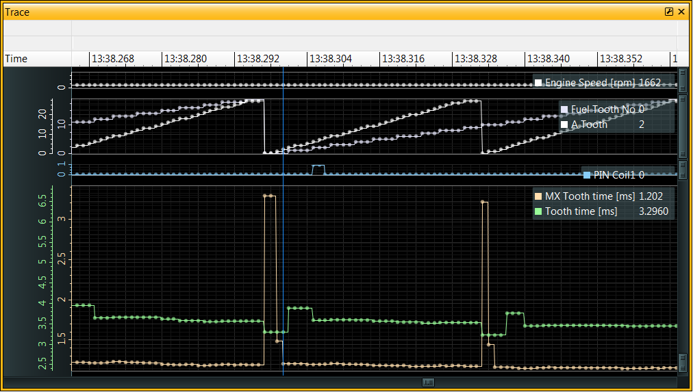
See the long tooth interval detected in MX Tooth Time when A Tooth = 0
The long tooth appears to be in 2 parts of 3.296 and 1.482 ms, with the regular teeth spaced at 1.185 ms.
This is from a 30-2 wheel so the missing tooth interval should be approximately 3x the regular teeth interval.
Notice that the Tooth Time channel has major discontinuities; it is expected that the internal teeth (decoded by the tooth control table) are regularly spaced and so a more constant value is expected here.
With the Crank Rising Edge and Crank Falling Edge swapped we get just a single long MX Tooth Time 3.754 ms, equal to 3 regular teeth (on a 30-2 wheel) as expected. The regular teeth are spaced at ~1.243 ms:
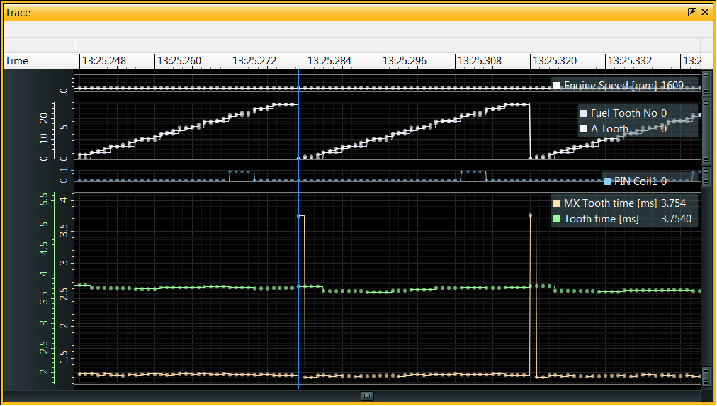
3.754ms / 1.243ms = 3.02 teeth
Also notice that the Tooth Time and A Tooth channels are smoother, meaning that the edges are interrupting the ECU more reliably.
If you are unable to start the engine and idle, it is possible to get the timing wheel running at a steady speed by removing the spark plugs (to avoid compression) and using the starter motor to turn the engine over. This will allow the ECU to log the crankshaft position data without the engine running. For safety, any injection and spark outputs can be disabled in the ECU calibration for this test.
T1 Filter Below - RPM value below which the T1 filter is active.T1 Low Sens Above - Reduces the sensitivity of the T1 input above this RPM value, can be useful for VR sensors.Crank Filter - Time window, in microseconds, for filtering edges on the crank sensor input.Tooth Short Ignore - Enables software filtering of short tooth intervals. This is useful for filtering out noise on the crank sensor input.Tooth Short Running - This is a percentage of the last valid actual tooth interval, edges detected that are less than this percentage are rejected.Tooth Short Start - When cranking (starting) the engine, before synchronization is achieved, Stat Sync'd == OFF, software filtering uses a fixed time interval for rejecting edges - edges detected that are less than this interval will be rejected.When running, Tooth Time x Tooth Short running is used to determine the minimum tooth interval that will be considered a valid tooth event.
The calculated value for the short tooth test is stored in A Tooth Short Test.
If a short tooth is detected, it will record this information in:
A Tooth Short [ms] - captures captures MX Tooth TimeA Tooth Short No - captures A ToothA Tooth Short Rev - captures Cam count MXThis information will be recorded regardless of whether Tooth Short Ignore is set.
A cam sensor is used to determine the position of the camshaft, typically relative to the Crank Sensor.
If the Sync Channel T option is changed during the cam sensor configuration, the ECU must be power-cycled before the change will have an effect. Before power-cycling, ensure that the calibration has been committed to Non-volatile memory (NVM).
If a camshaft position sensor is required, similarly to the crank sensor, it is usually a Hall effect sensor or a VR (Variable Reluctance) sensor. The sensor is typically connected to ECU timer T2 which has a software selectable pull-up resistor. It is possible to use a different timer input if required but T2 is the most common choice.
| Sensor Type | T2 Pull-up |
|---|---|
| Hall Effect / Optical | Yes |
| VR / Inductive | No |
As with the crank sensor the cam synchronization edge should be configured.
If you are planning on using the VVC (Variable Valve Control) features then T2 should be configured for both edges, with the appropriate edge for Cam or 4 stroke cycle synchronization selected by the Sync channel T option. VVC control would require configuration with the other direction edge where appropriate (VVC1 source T, VVC2 source T, VVCX1 source T, or VVCX2 source T).
For example:
| Option | Value |
|---|---|
| T2 Rising Edge |
ON |
| T2 Falling Edge |
ON |
| Sync channel T |
“T2 Rise” |
If not using T3-T12 timing inputs they can be switched off with T3 - T12 Disable to avoid any additional CPU overhead.
Like the crank sensor, the cam sensor can have hardware filtering applied to it:
T2 Filter Below - RPM value below which the T2 filter is active.T2 Low Sens Above - Reduces the sensitivity of the T2 input above this RPM value, can be useful for VR sensors.On 4 stroke engines where sequential injection and/or ignition is required, the ECU must synchronize to the correct revolution of the engine cycle so that the correct fuel and spark events are generated.
The crank wheel typically rotates once per revolution and therefore does not provide the ECU with enough information on its own.
However, the camshaft rotates once per cycle (2 revolutions of the crankshaft) and a sync signal from the camshaft can be used to determine the engine cycle.
The ECU counts the occurrence of rising or falling (or both) edges from the cam sensor.
The counter, typically T2R counter (rising) or T2F counter (falling), is captured at an actual crank tooth Sync Test A Tooth and is reset to zero to begin counting again; the counter will be reset every crank revolution at the specified tooth.
Example:

In this example with a 8-1 crank wheel, there are 2 rising edges in the 1st crank revolution and 1 rising edge in the 2nd crank revolution.
The synchronization test point may be adjusted using the Sync Test A Tooth option.
Sync Test A Tooth is the actual crank tooth number (i.e. not an internal tooth number) at which the camshaft counter is captured and reset to zero on every crank revolution. The value is captured into the Cam Tooth Count channel.
Sync Teeth is the number of Cam teeth expected at Sync Test A Tooth when testing for synchronization if the engine is within the expected half of the 4-stroke cycle.
If Sync Test A Tooth were set to 6 in this example (corresponding to the 7th tooth of the crank wheel, counting from 0), then the counter would be set to 2 in the first revolution and 1 in the second revolution.
Setting Sync Teeth to 2 would result in synchronization to be achieved on the 1st crank revolution. If set to 1 then synchronization would be achieved on the 2nd crank revolution.
During the ‘synchronization’ portion of the tooth control table, the captured counter value is tested against the Sync Teeth value.
It is essential that the cycle detection is unambiguous, otherwise the ECU may randomly synchronize to the wrong cycle.
It is recommended to use data logging and/or an oscilloscope to verify the configuration.
It is not possible to set Sync Test A Tooth to the missing tooth position, as the ECU would not detect an “A Tooth” at that point.
On variable cam control systems, the timing of the camshaft signal varies with respect to the crankshaft signal.
Considering the example diagram again, if the camshaft was in its most retarded position at that point then the ‘Cam’ signal could shift to the left by up to 80 degrees (almost 2 Actual Teeth in this example).

The original example with Sync Test A Tooth set to 6 would still be correct, when counting rising edges, for either cycle 1 or cycle 2 if the cam signal were shifted to the left by as far as 2 teeth.
However, suppose Sync Test A Tooth was set to 4. There would be multiple issues:
Sync Test A Tooth closely coincides with the cam signal, and there is a race between the crank signal and cam signal - small timing variations could cause unreliable detection of the cam signal.In both cases, the cycle detection would be highly unreliable.
Depending upon the cam sensor configuration, the ECU could be counting rising edges, falling edges or both.
The cam sensor edge direction may be selected by a combination of T2 Rising Edge, T2 Falling Edge and Sync Channel T.
It is possible to use timers other than T2 for cam synchronization, but T2 is the most common.
Engines with Variable Valve Control (VVC / VVT) would typically require both edges to be enabled with Sync Channel T set to either “T2 Rise” or “T2 Fall” so that only the rising or falling edge of the cam signal is used for engine cycle synchronization.
The edge selection may require adjustment to improve engine cycle detection.
If you are using a VR (Variable Reluctance) sensor for the Cam sensor then there may only be 1 valid edge due to the nature of signals from VR sensors - see Crank Sensor.
An optional feature is available to support synchronization within a single crank revolution.
If Sync 2 Active is set to ON, then the cycle shall also be matched using Sync 2 Teeth.
If Cam Tooth Count matches Sync 2 Teeth then synchronization will be achieved (Stat Sync'd will be set to ON) and the value of Sync 2 Fuel Tooth will be placed into Fuel Tooth and the value of Sync 2 Spark Tooth will be placed into Spark Tooth to ‘jump’ these important clocks to the next half of the cycle.
Considering the example again:
For sequential injection + ignition with 4 internal teeth per revolution, this example ECU could be configured with:
| Option | Value |
|---|---|
| Sync Teeth |
2 |
| Sync Test A Tooth |
6 |
| Sync 2 Active |
ON |
| Sync 2 Teeth |
1 |
| Sync 2 Fuel Tooth |
4 |
| Sync 2 Spark Tooth |
4 |
| Fuel Teeth |
8 |
| Spark Teeth |
8 |
| Option | Description |
|---|---|
| Start No Cam Sync |
The ECU will not attempt to synchronize to the camshaft while cranking (starting) the engine. |
| Sync Channel T |
Selects Cam synchronization input timer (e.g T2 Rise) |
| Sync Teeth |
Number of teeth expected to unambiguously identify 1 revolution in the engine cycle. Must be set to 0 if not using a Cam Sync input. |
| Sync Test A Tooth |
The actual crank tooth number at which the camshaft counter is captured and reset to zero. This is the actual crank tooth (A Tooth) number, not the internal tooth number. Care should be taken, particularly with systems using VVC, to ensure reliable detection across the range from most retarded to most advanced camshaft positions. |
| Cam Tooth Count |
Value of the sync channel (e.g. T2R counter) when A Tooth reaches Sync Test A Tooth |
| Cam Tooth MX |
Value of Cam Tooth Count when ‘MX’ (Missing / Extra tooth) synchronization tested. |
| Sync 2 Active |
Enabled Sync 2 feature. |
| Sync 2 Teeth |
Number of teeth to identify 2nd revolution in the engine cycle. |
| Sync 2 Fuel Tooth |
Value to set in Fuel Tooth if Sync 2 is achieved. Jumps the injection ‘clock’ to the next half of the cycle. Should be set to the number of internal teeth per revolution, if sequential injection is required. |
| Sync 2 Spark Tooth |
Value to set in Spark Tooth if Sync 2 is achieved. Jumps the ignition ‘clock’ to the next half of the cycle. Should be set to the number of internal teeth per revolution, if sequential ignition is required. |
There is a difference between actual teeth on the crankshaft wheel and internal teeth used by the ECU for triggering ignition or injection events.
Internal teeth always coincide with actual teeth but they are arranged such that they are at evenly spaced crank angles.
Events from ‘actual teeth’ on the crankshaft wheel cause the ECU’s CPU to be interrupted. The ECU decides whether these events are ‘active edges’ aka ‘internal teeth’ that may be used for triggering ignition or injection events.
If using a missing / extra tooth strategy, the actual tooth events are not evenly spaced. The ECU is able to detect this un-even spacing to identify missing / extra teeth.
If the engine cycle can be determined from a camshaft sensor, and sequential injection or ignition is required, then the Fuel Teeth and Spark Teeth options should wither be set to the same value as the number of internal teeth (e.g. wasted spark) or to double the value (sequential).
Once the crank / cam sensors are configured, the synchronization strategy and tooth pattern must be set up to be able to synchronize the ECU with the engine.
When cranking / starting the engine, the ECU will initially be in an unsynchronized state. The ECU will not be able to determine the engine cycle position until synchronization is achieved.
When the ECU reaches the synchronized state, the Stat Sync'd channel will be set to ON.
During cranking, the ECU uses a different control strategy to normal running.
The most common synchronization strategy is to use a Missing tooth (or eXtra tooth) on the crankshaft wheel, GEMS ECUs refer to this as the Sync MX strategy.
There are 4 synchronization strategies available, controlled by 3 options. These options must be set in a mutually exclusive way:
Sync Crank S count if possible.Sync Cam Count, counts the number of crankshaft teeth between camshaft teeth.Tooth Control table and used camshaft signal to subdivide the engine cycle.The Sync MX strategy is the most common synchronization strategy. It uses a missing tooth / teeth (or an extra tooth) on the crankshaft wheel to determine the engine cycle position.
The following options are used to detect the missing or extra tooth:
| Option | Description |
|---|---|
| Sync MX |
ON |
| Sync Cam Count |
OFF |
| Sync Crank S Count |
OFF |
| Sync Crank Divider |
OFF. This option has a major impact on timing interrupts and changing it requires an ECU reset. |
| Missing |
Number of missing or extra teeth. Allowed values 0, 1, 2, -1. A value of -1 indicates the wheel uses an extra tooth (e.g. Honda 12+1). |
| MX Sync Test |
Number of actual teeth before the missing tooth since the last missing section. For wheels with only 1 missing section or 1 extra tooth, set this to the physical number of teeth - 1. So for e.g. 36-2 this should be 34-1, which is 33. For more complex wheels with multiple missing sections (e.g. Rover K), set to the longest run of teeth without any missing teeth between them. |
| MX Time |
Threshold for Missing Tooth detection. Percentage of prior tooth interval time to predict minimum interval to next tooth. |
| Start MX Time |
Threshold for Missing Tooth detection (when cranking). |
| Sync Teeth |
Cam Synchronization, count of Cam sensor events that must occur to reset Fuel Tooth No and Ign Tooth No. |
| Test not Sync'd |
Set to ON so that while cranking, all opportunities are used for synchronization |
| Sync off Above |
Ignore the Cam sync above the specified Engine Speed, if non zero. This may be required at higher RPMs if cam and crank interrupts can interfere with each other, reducing timing precision. |
| Sync Err R/S |
Result in loss of synchronization (Stat Sync'd => OFF) if this number of Sync errors are detected. |
| Sync Test A Tooth and Sync Test A enable |
move cam synchronisation decision at a specific A Tooth, rather than synchronisation test at last valid entry in Tooth control table. This is may be useful with variable cam control systems, where the cam signal used for synchronisation crosses the old fixed decision point. Only used with “Sync MX” Strategy. |
Using a value for ‘Missing’ of 1 may be acceptable for wheels with 2 missing teeth in a row, depending upon the value of MX Time.
The value of MX Time is a balance between the maximum tolerable deceleration of the engine and the ability to detect the missing tooth.
MX Time or Start MX Time is used to make d Tooth Time that is compared with the new tooth time to detect the missing or extra tooth. If detected it is displayed in Miss Time.
This is a scaling factor for the tooth interval for giving a lower bound on when the next tooth should arrive.
If there are missing teeth then either 1 or 2 whole intervals will be added to this value, depending upon the value of Missing. If there is an extra tooth then no extra intervals are added.
When the first tooth after the missing section on the wheel is detected then this deadline should be missed - and the ECU will consider this event as having just passed the missing tooth.

For each time the Tooth Control table is successfully processed, the ECU will decrement the Sync good count channel until it reaches 0.
Simplest synchronising strategy, where possible use Sync Crank S Count.
Where Cam Count = Sync teeth
Cam count is the number of cam teeth between crank teeth, as in old Subaru pattern and Dodge Viper.
24 even crank teeth per engine cycle with 1 cam tooth.
3 crank teeth per cylinder event.
Where SS Tooth No = MX Sync test and Sync Tooth = Sync teeth
SS Tooth No is the number of internal crank teeth between cam teeth.
Sync tooth is the value of Fuel tooth at the synchronising cam tooth.
| Option | Description |
|---|---|
| Sync Crank S Count |
ON |
| Sync MX |
OFF |
| Sync Cam Count |
OFF |
| Sync Cam Width |
OFF |
| Sync Crank Divider |
OFF. This option has a major impact on timing interrupts and changing it requires an ECU reset. |
| Missing |
Set to 0 since there are no missing / extra teeth. |
| Sync Teeth |
|
| MX Sync Test |
24 even crank teeth per engine cycle with 3 cam teeth at TDC for only 3 cylinders.
24 even crank teeth per engine cycle with 1 cam tooth.
Edge at 45deg 4 teeth cycle, no cam synchronisation.
Adjust ignition range for useful +/45 degrees = 0.5
4 even crank teeth per engine cycle with 2 cam teeth.
Old synchronization strategy used with timing wheels with a high number of teeth without any missing/extra teeth. The camshaft sensor is used to identify the engine cycle position.
| Option | Description |
|---|---|
| Sync MX |
OFF |
| Sync Cam Count |
OFF |
| Sync Crank S Count |
OFF |
| Sync Cam Width |
ON |
| Sync Crank Divider |
ON. This option has a major impact on timing interrupts and changing it requires an ECU reset. |
| Missing |
Set to 0 since there are no missing / extra teeth. |
| Crank Divider |
Divisor for reducing crank teeth to internal teeth. |
| Cam Width Test |
Number of subdivided teeth that must be seen in order to synchronize. |
| Sync Teeth |
Copied to Crank Div Sync Err if synchronization is lost; number of good sync’s required to set Stat Sync'd to ON. |
If the Sync Cam Width option is ON, synchronization is achieved if Cam Width = Cam Width Test when the Cam interrupt occurs.
In some ECUs this may be MX Sync test.
If the Sync Cam Width option is OFF then synchronization would achieved if SS Tooth No = Cam Width Test when the Cam interrupt occurs. However, SS Tooth No is only set when Sync Crank Divider is OFF or during crank interrupt with the Sync Crank S Count strategy enabled. So this mode is no longer of use in recent firmware versions.
In case of loss of sync, Crank Div Sync Err is set to the value of the Sync Teeth and decremented for each successful Cam synchronization. When Crank Div Sync Err reaches 0, the ECU will consider the engine to be synchronized and will set Stat Sync'd to ON.
Pulse Acc count T1 (aka PA Count T1) is captured at start of T2 interrupt, stored in PA count1 temp. This counts T1 events (crank teeth).
Cam Width receives the number of subdivided crank teeth that have occurred since the last Cam sensor event.
These are historical examples that may contain errors and have not been re-tested on modern hardware.
135 crank teeth on ring gear, one sync pulse at 1/2 engine speed.
MX Sync Test on some ECUs)360 crank teeth (high speed), 4 cylinder slots of different widths, equivalent to 2,3,5,or 5 crank teeth.
Use only fast falling edges for crank (T1) and cam (T2).
The main goal of the Tooth Control table is to subdivide the physical timing wheel teeth (actual teeth) into regularly spaced internal teeth.
The RPM Pickup wizard can be used to calculate the Tooth Control table values, given some common timing wheel types.
The Tooth Control table is a low-level ECU feature that is not obvious but essential to understand if needing to accommodate unusual tooth patterns.
Each site in the Tooth Control table corresponds to the sequence of ECU interrupts (events) from actual teeth passing the crank sensor and are therefore not necessarily evenly spaced in time or angle; there will not be any events in the missing section of the wheel or there may be an extra tooth. Some timing wheels have more than one missing teeth section.
The aim is to select from these events an evenly spaced real-world pattern of internal teeth that can be used to schedule fuelling and ignition events. The internal teeth are used to subdivide the engine cycle into equal parts, and the ECU will increment internal tooth counters for each internal tooth detected, with separate counters for fuelling and ignition.
If using a wheel with 2 missing teeth in a row, for example, then the actual teeth will need to be divided by at least 3 (possibly more) to ensure that no internal teeth fall within the missing section and are also evenly spaced in terms of crank angles. Each internal tooth must coincide with an actual tooth passing the sensor; i.e. an interrupt/event occurs in the ECU for each internal tooth.
It is common to subdivide the timing wheel into 12 internal teeth. For example, with a 36-2 wheel that has 2 missing teeth in a row this can be divided by 3 into 12 equally spaced internal teeth that all coincide with actual teeth.
When actual teeth are detected, the ECU will increment A Tooth and use the value to look up the corresponding site in the Tooth Control table.
Each value in the table is composed of 3 digital ‘bits’ (1/0):
| Value | Bits | Function |
|---|---|---|
| 0 | 000 | Do nothing. |
| 1 | 001 | Active Edge (Internal Tooth). |
| 2 | 010 | Alternate Edge (Used for Crank Alt Fire mode). |
| 3 | 011 | Reset A Tooth, if loss of sync. Indicates the end of the table. |
| 4 | 100 | Test for synchronization. |
| 5 | 101 | Active Edge (Internal Tooth) + test for synchronization. |
| 6 | 101 | Alternate Edge + test for synchronization. |
| 7 | 111 | Reserved (do not use this value). |
Unless all sites in the table are required, the value ‘3’ should be placed at the end of the table so that loss of synchronization can be detected; if A Tooth overruns the valid section of the table then the ‘3’ shall be encountered and the ECU will reset A Tooth to 0. The channels Sync Error and Timing Error will be incremented if this event occurs.
It is expected that the synchronization event(s) will be detected before the ‘3’ value is encountered, which would also result in A Tooth being reset to 0.
Active edges (internal teeth) are used to schedule fuelling and ignition events and are indicated by either ‘1’ or ‘5’ in the table. The ECU increments internal tooth counters Fuel Tooth No and Ign Tooth No when an active edge (internal tooth) is encountered in the Tooth Control table.
The Synchronization Test bit (100), when set, will cause the ECU to test for synchronization. This allows for some reduction of CPU load when running at higher RPMs by skipping synchronization checks on all tooth interrupts (events) (which would be occurring much more frequently). This bit is normally set in the tooth control values near the end of the table where the missing / extra tooth is approaching, though for some other patterns there could be multiple synchronization points.
When not synchronized (Stat Sync'd == OFF), the ECU can be configured to test for synchronization on all actual teeth by setting Test Not Sync'd to ON (recommended).
The ECU may be configured to output a tachometer signal to drive an external tachometer. The signal is a square wave with a frequency proportional to the engine speed.
Tachometer state change events are inserted into the Tacho Edge table. They should be evenly spaced and typically there should be 4 state changes per revolution (i.e. 2 pulses per rev), depending upon the tachometer input requirements.
It is generally best, therefore, to place the state changes at the same A Tooth numbers as equidistant ‘active edges’ in the tooth control table, assuming that it is possible to do so.
The Tacho Pin option specifies which ECU pin the tachometer signal is output from. Check the ECU pinout to determine which pin number this should be set to.
Changing the Tacho Pin option requires an ECU reset to take effect.
If using the RPM Pickup wizard, the Tachometer output can be calculated for you given a pulse-per-rev value. The RPM Pickup wizard assumes that Wheel Teeth is equal to the number of internal teeth.
Starting the engine may be controlled by the ECU, in response to configurable input signals.
To start the engine, the fuel pump must be powered, the engine is primed with fuel, the starter motor must turn the engine over, timing wheel(s) synchronization must be established, and ignition and injection events must then occur with sufficiently precise timing to ensure that the engine starts powering itself.
Cold engines require a richer fuel mixture due to reduced fuel vaporization and increased oil viscosity. The ECU provides methods of enriching the fuel mixture during cranking and warm-up.
When stopping the engine, the ignition key is turned off, and the ECU will stop fuel injection, park the idle stepper motor, and turn off power to the fuel pump and the ECU itself (Main Relay control).
Starter In is a configurable switch input to request the starter motor to run. This is typically connected to the ignition key in the ‘crank’ position. If starting of the engine is managed externally, then Starter In may be left un-configured.
Starter Out is a configurable output that will be energized when the starter motor should be turned on. This is typically connected to a relay coil that switches the high current supply to the starter motor.
Starter Time out configures the maximum time that the starter motor will be energized. This is a safety feature to prevent damage to the starter motor if the engine fails to start.
Starter Exit Speed configures the engine speed at which the starter motor will be turned off, assuming that the engine has started turning itself over. Starter motors turn the engine over at a relatively low speed (typically up to 500 RPM) - the motor should be turned off as soon as the engine is running under its own power to avoid damage to the starter motor and unnecessarily draining the battery.
The cranking state is indicated by the Stat Cranking channel. The ECU will report that it is in the ‘Cranking’ state as soon as it is turned on, even though the engine may not actually be turning.
The ECU indicates that the engine is actually in motion if Stat Running is ON. The ECU will trigger any ignition or injection events until Stat Sync'd is ON, indicating that the ECU has synchronized with the engine timing wheel(s). Synchronization is required to ensure that ignition and injection events occur at the correct time in the engine cycle.
When starting an engine, the ECU must compute an Engine Speed value prior to fully synchronizing with the crankshaft / camshaft timing wheel(s). The ECU estimates the engine speed using fewer crank teeth than a full engine cycle when Stat Sync'd is OFF, see and Engine Speed (RPM) Calculation for details. This initial speed calculation uses Start Actual Teeth, Start Actual Teeth <2, Speed mul and Speed Cycle/rev.
Start Crank Teeth configures the number of ‘synchronized’ teeth (T1 Count Sync’d) that must be detected before the ECU will exit cranking mode.
The T1 Count Sync'd channel is the number of actual crank teeth seen since engine synchronization was achieved and counts up until it reaches 255, at which point it stops counting. This channel can be useful to monitor short-term loss of synchronization; it is reset to zero if synchronization is lost.
Start min Speed configures the minimum engine speed that must be exceeded before the ECU will allow ignition events to occur. Ignition events will need to start while the engine is being turned over by the starter motor, so this value should be set to a value that is achievable by the starter motor.
Crank Exit configures the engine speed at which the ECU will exit the cranking state. This should be set to a value lower than the minimum idle speed of the engine, but higher than the speed that can be achieved by the starter motor. It indicates that the engine is running under its own power.
Ignition timing may be adjusted during cranking using the Start Ignition option.
Due to compression within the engine, the starter motor is unlikely to be capable of turning the engine smoothly, so wider missing / extra tooth tolerances may be required to account for the more significant variations in engine speed during cranking.
Option Start MX Time is used in place of MX Time when starting to determine the tolerance between crank teeth. Its value will depend upon the type of crank wheel (e.g. Missing or eXtra tooth) / sync strategy.
For configurations that normally use sequential ignition, cam synchronization may be ignored during cranking by setting Start No Cam Sync to ON, effectively running the engine in wasted spark mode during cranking.
Engines using plastic inlet manifolds should not use this feature as the potential for backfire may severely damage / blast off the manifold.
The Start Pulse feature is not commonly required on modern engines; configuring the ECU to provide extra fuel during cranking is usually sufficient and safer.
To use the Start Pulse feature, the cranking position of the ignition key should be wired to the ECU, with the corresponding input pin selected in the Start Pulse pin option. Note: Start Pulse pin can be configured as an active low by making the option negative.
When the start pulse pin is asserted (and Stat Cranking is ON), the ECU will fire all fuel injectors simultaneously with a Start Pulse duration of fuel.
Start Pulse is taken from the Start Pulse table, which is indexed by the Coolant temperature channel.
The starter will turn the engine, and the ECU will try to synchronize with crank and cam timing signals.
The Engine Speed channel will be calculated after some timing wheel events have occurred, see Engine Speed (RPM) Calculation for details.
When the engine is synchronized, indicated by Stat Sync'd = On, the ignition and fuel injection events will be allowed.
if Start Pulse pin was not detected the first cycle of injections will be extended by Start Pulse duration. After Start rev counter will increment until Crank Exit speed is exceeded and normal running established, where upon the After Start timer will start.
The ignition key is turned to Off, the Main Relay Off timer starts.
The following options specify time durations for shutdown tasks that are performed in sequence:
Main Relay Stop Eng - fuel injection stopped, may take several seconds for the engine to run down.Main Relay Park IAC - resets and parks idle stepper motor.Main Relay Kill Pwr - turns off outputs - Out Main Relay, and - Out Main Relay 2.This time must be long enough for idle motor to complete parking.
Main Relay Safety will delay the turn off if there is non-volatile write of calibration data indicated by Error EE Checksum if option Auto EE is On.
If the ignition key is returned to on position, after Main Relay Off exceeds Start Pulse Rearm Time, and Start Pulse Rearm and Main Relay Off Restart are On, the fuel pump will run again for Fuel Pump Prime seconds, and Start Pulse Pending will go On.
Once the synchronization strategy is configured and the ECU is able to synchronize with the engine, the engine speed (RPM) can be calculated.
The Engine Speed channel is calculated using the time intervals of crankshaft position sensor readings.
A value must be specified in the Speed mul option otherwise Engine Speed will read zero.
The Wheel Teeth option defines how many internal teeth time intervals are summed to produce the Rev Time MSB and Rev Time channels. Depending upon whether Wheel Teeth is equal to the number of internal teeth per revolution determines whether or not Rev Time is really the total time for one revolution of the crankshaft (it may not be).
If Wheel Teeth was 2x the number of internal teeth per revolution then the engine speed would be summed over 2 revolutions of the crankshaft.
If the Speed cycle/Rev option is ON then the speed is derived from 150ms/“Rev Time” instead of 300ms/“Rev Time”, which can act as a tradeoff between maximum engine speed and precision.
The Speed mul option is used to scale the result to a correct RPM value, depending upon the combination of the settings.
Valid settings, e.g. for a calibration with 12 internal teeth:
| Wheel Teeth |
Speed mul |
Speed Cycle/rev |
Max Engine Speed |
|---|---|---|---|
| 12 (1 rev) | 50% | OFF | 12799 rpm |
| 12 (1 rev) | 100% | ON | 25599 rpm |
| 24 (2 revs) | 100% | OFF | 25599 rpm |
The Pickup comp option compensates for fixed timing drift. The ECU’s calculated RPM value can be compared to that measured using a calibrated tachometer to determine the correct value for this option.
When the engine is starting, the ECU will be in an unsynchronized state and therefore can’t identify the internal teeth, so a different strategy is required to calculate the engine speed.
This strategy is less accurate that using internal teeth - actual crank teeth may be irregularly spaced due to missing / extra teeth.
Times between physical teeth (‘actual’ teeth) are measured between crank wheel sensor events. Engine speed can be estimated over as few as 2 teeth, but accuracy improves with more teeth. A maximum of 7 teeth intervals may be used to estimate the engine speed during cranking.
Start Actual Teeth configures the number of tooth times to sum for the starting Engine Speed calculation. Until this number of teeth have been detected, the engine speed will be zero.
Start Actual Teeth <2 is a ’left-shift’ - the number of times to double the partial rev-time such that it represents something close to either a single revolution or two revolutions (a 4-stroke engine cycle) of the crankshaft, depending upon the calculation strategy.
Rev Timenot sync’d = Tcycle | rev = T‘Start Actual Teeth’ * 2‘Start Actual Teeth <2’
Depending upon the engine speed calculation strategy, rpm will be estimated over either one or two revolutions of the crankshaft, so the Start Actual Teeth and Start Actual Teeth <2 must take into account the ratio between Wheel Teeth and the number of actual-vs-internal-teeth derived from the crankshaft timing wheel using the Tooth Control table.
For example a few possible settings for Start Actual Teeth and Start Actual Teeth <2 are shown below, derived from a 36-2 timing wheel configuration:
| Item | Value |
|---|---|
| Crankshaft timing wheel | 36-2 (34 physical teeth) |
| Subdivider (physical teeth per internal tooth) | 3 |
| Internal teeth per revolution (Tooth Control) |
12 = (36 / 3) |
| Wheel Teeth |
24 = (12 * 2) |
| Engine speed calculated over | 2 revs |
| Speed mul |
100% |
| Speed Cycle/rev |
OFF |
| Target estimation tooth count | 72 = (36 * 2), 2 revs |
| Reduce to value near 7 by successive divide by 2 | 36 = (72 / 2) |
| 18 = (72 / 4) | |
| 9 = (72 / 8) | |
| 4.5 = (72 / 16) | |
| Start Actual Teeth (max 7) |
7 = limit 9 to 7 |
| Start Actual Teeth <2 |
3 = log2(8) |
| Estimated over | 56 = (7 * 8) teeth, 1.65 revs |
| Error | -22% = (56 / 72) |
| Start Actual Teeth (max 7) |
4 = round down 4.5 |
| Start Actual Teeth <2 |
4 = log2(16) |
| Estimated over | 64 = (4 * 16) teeth, 1.88 revs |
| Error | -11% = (64 / 72) |
| Start Actual Teeth (max 7) |
5 = round up 4.5 |
| Start Actual Teeth <2 |
4 = log2(16) |
| Estimated over | 80 = (5 * 16) teeth, 2.35 revs |
| Error | +11% = (80 / 72) |
The various options for calibration here are a trade-off between accuracy and precision. While a lower Start Actual Teeth value may give a more accurate engine speed (closer to the actual RPM value), it may be less precise than if it had been calculated over more teeth.
The accuracy of the engine speed during this phase is not all that important - any options that depend upon it can be adjusted accordingly. The precision of the engine speed is arguably more important, especially when there are missing / extra teeth on the timing wheel - but the extra precision it does mean that it will take more teeth passing the sensor to achieve a non-zero engine speed value.
Crankshaft timing wheel is a 36-2 (34 actual teeth) and Wheel Teeth is set to 12 (1 internal tooth per 3 actual teeth), then to estimate the engine speed over a single revolution of the crankshaft, Start Actual Teeth should be set to 12 * 3 = 36 and Start Actual Teeth <2 should be set to 0.
Ignition events occur relative to crankshaft rotation angles.
Ignition angles are typically measured in degrees relative to Top Dead Center (TDC) of the compression stroke. Internally, the ECU works in units of virtual ‘internal teeth’, which are proportional to the crankshaft rotation angle.
Various items in the calibration may adjust the ignition timing (advance or retard it) relative to TDC.
See RPM Pickup for a discussion on how the ECU determines the crankshaft position, internal teeth, and the relationship to rotation angle.
Once the RPM Pickup has been calibrated, the ignition drivers may be assigned to the engine cylinders.
The options IGN1 to IGN8 enable the associated ignition driver circuit.
Whilst it is desirable for software IGN numbers to refer to cylinder numbers, in practice this may not be possible due to multiplexing of the ignition drivers.
Some newer ECUs use Coil 1 to Coil 8 instead of IGN1 to IGN8. The options ar are assigned to the ignition driver circuits in reverse sequence to avoid multiplexing being used on the lower Coil numbers (allowing Coil N to match Cylinder N on any engine up to 6 cylinders, where there is a single ignition driver per cylinder, if desired).
IGN Tooth 1 to IGN Tooth 8 controls the relative angle of individual ignition driver triggers (firing angles) - essentially these options define the firing order.
The adjusted ignition timing calculation is added to these per-driver angles to result in a final ignition timing value for each driver (producing Spark 1 Total to Spark 8 Total).
Depending on the ECU hardware, multiplexing of ignition triggers may be required due to limitations on the number of Timer Output Compare (TOC) pins on the CPU in the ECU.
The EM80 ECU has 6 TOC pins available for controlling up to 8 ignition drivers, so some additional non-timer pins are used to share 2 TOCs between 4 ignition circuits. On EM80, the IGN1 and IGN3 circuits are multiplexed and so are IGN2 and IGN4.
flowchart LR
    IGMUX11-->AND1(["&"])
    TOC1-->AND1
    TOC1-->AND2
    IGMUX12-->AND2(["&"])
    AND1-->IGN1
    AND2-->IGN3
    IGN1-->LM4{{LM4}}
    IGN3-->LM3{{LM3}}

    IGMUX21-->AND3(["&"])
    TOC2-->AND3
    TOC2-->AND4
    IGMUX22-->AND4(["&"])
    AND3-->IGN2
    AND4-->IGN4
    IGN2-->LL2{{LL2}}
    IGN4-->LM2{{LM2}}

    TOC3-->IGN5
    IGN5-->RH3{{RH3}}

    TOC4-->IGN6
    IGN6-->RG3{{RG3}}

    TOC5-->IGN7
    IGN7-->RH2{{RH2}}

    TOC6-->IGN8
    IGN8-->RH1{{RH1}}
Multiplexed IGN triggers place some restrictions on the assignment of IGN driver circuits to physical engine cylinders.
Multiplexed IGN circuits must be mutually exclusively triggered. The consequences of timing overlap here could be severe engine knock / pre-ignition.
To give the maximum amount of timing flexibility we either want to avoid using both IGN drivers within multiplexed pairs, or ensure that multiplexed drivers (e.g. IGN1 and IGN3 on EM80) are assigned to physical cylinders that have TDC that is 360 degrees apart from one another.
It should be possible to calculate if timing overlap is possible using the following formula if necessary:
‘IGN Tooth 1’ + ‘Dwell Max’ >= ‘IGN Tooth 3’
If the above condition is violated, then the IGN circuits are not mutually exclusive and the ECU will not be able to control the ignition timing correctly.
If the engine is running wasted spark then it may be acceptable to fire the multiplexed IGNs at the same time if they are assigned to the correct cylinders.
You may find that assigning Cylinder 1 to IGN1 is a good starting point for the ignition circuit assignment. This will allow the use the “Spark Total 1” channel to refer to Cylinder 1 as a general indication of ignition advance/retard by convention.
The rest of the IGN circuits may then be assigned, taking into account the firing order and firing angles of the engine.
On a 4 cylinder engine, one option would be to then use IGN2, IGN5 and IGN6 (skipping the multiplexed IGN3 and IGN4), to avoid any chance of overlap in the multiplexer.
Given an even firing order of 1-3-4-2, the IGN + cylinder assignment for this strategy could be as follows:
| Cylinder | IGN Driver | Angle | IGN Tooth (if 12 teeth / rev) |
|---|---|---|---|
| 1 | IGN 1 = ON | 0° | IGN Tooth 1 = 0.0 |
| 2 | IGN 2 = ON | 540° | IGN Tooth 2 = 18.0 |
| 3 | IGN 5 = ON | 180° | IGN Tooth 5 = 6.0 |
| 4 | IGN 6 = ON | 360° | IGN Tooth 6 = 12.0 |
| IGN 3 = OFF | |||
| IGN 4 = OFF | |||
| IGN 7 = OFF | |||
| IGN 8 = OFF |
On 6 cylinder engine, we could follow the same pattern and use IGNs 1,2,5,6,7,8.
Of course we could still use the multiplexor for 4 cylinder, provided we arrange for IGN1 and IGN3 to be 360 degrees apart and the same for IGN2 and IGN4.
Given an even firing order of 1-3-4-2, the IGN + cylinder assignment could be as follows:
| Cylinder | IGN Driver | Angle | IGN Tooth (if 12 teeth / rev) |
|---|---|---|---|
| 1 | IGN 1 = ON | 0° | IGN Tooth 1 = 0.0 |
| 2 | IGN 4 = ON | 540° | IGN Tooth 4 = 18.0 |
| 3 | IGN 2 = ON | 180° | IGN Tooth 2 = 6.0 |
| 4 | IGN 3 = ON | 360° | IGN Tooth 3 = 12.0 |
| IGN 5 = OFF | |||
| IGN 6 = OFF | |||
| IGN 7 = OFF | |||
| IGN 8 = OFF |
On an 8 Cylinder engine we would be forced to use the multiplexed IGNs in any case, so careful assignment if IGNs will be required to ensure optimal phase separation of timing signals.
For example, for an 8 cylinder engine with a firing order of 1-8-4-3-6-5-7-2, the IGN + cylinder assignment could be as follows:
| Cylinder | IGN Driver | Angle | IGN Tooth (if 12 teeth / rev) |
|---|---|---|---|
| 1 | IGN 1 = ON | 0° | IGN Tooth 1 = 0.0 |
| 2 | IGN 8 = ON | 630° | IGN Tooth 8 = 21.0 |
| 3 | IGN 7 = ON | 270° | IGN Tooth 7 = 9.0 |
| 4 | IGN 5 = ON | 180° | IGN Tooth 5 = 6.0 |
| 5 | IGN 2 = ON | 450° | IGN Tooth 2 = 15.0 |
| 6 | IGN 3 = ON | 360° | IGN Tooth 3 = 12.0 |
| 7 | IGN 6 = ON | 540° | IGN Tooth 6 = 18.0 |
| 8 | IGN 4 = ON | 90° | IGN Tooth 4 = 3.0 |
The ignition timing range is the difference between the maximum and minimum ignition angles that may be specified in the calibration.
The option Ign Range specifies the number of internal teeth over which the ignition may be adjusted. The ECU uses this value to scale ignition timing adjustments to the ECU’s internal working units (fractional internal teeth).
For correct ECU operation, the Ign Range option must be set correctly.
The Ign Advance Scalar and Ign Advance Offset options are used to convert internal teeth to degrees and have no impact on the internal operation of the ECU.
The range can be tested using option Ignition Fixed to see the maximum advance / retard that can be achieved given Ign Advance Scalar and Ign Advance Offset.
Ign Range should be set to:
"Ignition Range (Degrees)" * "Internal Teeth" / 360Where Ignition Range, is:
"Max Advance Degrees BTDC" + "Max Retard Degrees ATDC"</code></pre>For most GEMS ECUs, given a known advance / retard value, the Ign Advance Scalar and Ign Advance Offset options can be calculated as follows:
"Ign Advance Scalar" = ("Max Advance" + "Max Retard") / 127

"Ign Advance Offset" = ("Max Advance" - 63.5) * "Ign Advance Scalar"If you do not have a base calibration for your engine where the timing alignment is pre-configured, the timing adjustment may be calibrated with the assistance of a timing light (strobe) that is triggered by the ignition signal (spark plug) on cylinder #1.
The ECU calibration should be set such that it is not trying to advance or retard the ignition timing. This may be achieved by setting option Ignition Fixed to a desired advance value and either setting Ignition Fixed Switch to “Always ON” or setting Ignition Fixed Speed to a higher RPM than you are expecting to reach. The channel Ignition Fixed will display ON if the ECU is running at a fixed ignition advance value.
Fixed ignition advance mode overrides any ignition adjustments except for Spark Sync and the per-ignition offsets (e.g. IGN Tooth 1 or Coil 1 Tooth etc, depending upon the ECU in question).
TDC should be accurately marked on the crankshaft timing wheel or flywheel. The strobe will illuminate the timing mark(s) on the wheel when the ignition event occurs, allowing the timing angle to be determined.
If the engine is unable to start then it is still possible to use a strobe but the spark plugs should be removed from the cylinders to avoid compression in the engine which would otherwise make the rotation speed inconsistent. The spark plugs should still be attached to the HT leads and attached to the engine earth. Once the engine is running, the timing adjustment process should be repeated for more accurate results.
Note that systems running wasted spark will have 2 ignition events per cycle, so ignition timing figures shown on the strobe light should be halved.
The Spark Sync option may be used to apply a ‘global’ fixed adjustment (trim) to the ignition timing, so that the timing mark may align with a desired advance value.
One strategy for configuring the timing would be to use Spark Sync as representing the most advanced firing point after the syncronization point. i.e. it is TDC° - Max Advance°.
VR sensors and coils may introduce a small fixed timing drift, which can be compensated for with the Pickup comp option. This is a temporal adjustment rather than being related to angle (Spark Sync). If you notice that the ignition advance is changing with RPM then it may be compensated with this option.
For engines that must run at very high RPMs or have many teeth on the crank wheel, the T1 Delay Time +3/16 Tooth option may be used to account for the processing time of the ECU.
These options will affect all timing calibrations so should be configured early in the calibration process.
| Option / Channel | Description |
|---|---|
| T1 Delay Time +3/16 Tooth |
Account for processing time when a tooth interrupt occurs. For high tooth rate / high RPM, setting this option changes the worst case processing window from 1/16th of a tooth to 1/4 of a tooth. |
| Ignition Fixed channel |
If set to ON, indicates that the ECU is running a fixed advance value, from the Ignition Fixed option. |
| Ignition Fixed |
Fixed ignition advance value to use when Ignition Fixed is ON. |
| Ignition Fixed Switch |
Switch input for running fixed ignition advance. This could be set to “Always ON” |
| Ignition Fixed Speed |
Engine speed below which the ECU shall run a fixed ignition advance value. This may be useful during starting or idling. |
| Spark Sync |
Trim / ‘Reference Point’ value for ignition timing. Base value to which advance / retard adjustments are added, to give a final absolute time for the next ignition event. |
| Fuel Sync |
Not relevant to ignition timing but similar to Spark Sync for adjusting injection timing. |
| Spark 1 Total Coil 1 Total |
The final ignition advance angle for the 1st ignition driver circuit. |
| Spark 2 Total Coil 2 Total |
The final ignition advance angle for the 2nd ignition driver circuit. |
| Spark 3 Total Coil 3 Total |
The final ignition advance angle for the 3rd ignition driver circuit. |
| Spark 4 Total Coil 4 Total |
The final ignition advance angle for the 4th ignition driver circuit. |
| Spark 5 Total Coil 5 Total |
The final ignition advance angle for the 5th ignition driver circuit. |
| Spark 6 Total Coil 6 Total |
The final ignition advance angle for the 6th ignition driver circuit. |
| Spark 7 Total Coil 7 Total |
The final ignition advance angle for the 7th ignition driver circuit. |
| Spark 8 Total Coil 8 Total |
The final ignition advance angle for the 8th ignition driver circuit. |
| Spark Out 1 Coil Out 1 |
The final absolute (fractional) internal tooth at which the ignition event shall occur for the 1st ignition driver circuit. |
| Spark Out 2 Coil Out 2 |
The final absolute (fractional) internal tooth at which the ignition event shall occur for the 2nd ignition driver circuit. |
| Spark Out 3 Coil Out 3 |
The final absolute (fractional) internal tooth at which the ignition event shall occur for the 3rd ignition driver circuit. |
| Spark Out 4 Coil Out 4 |
The final absolute (fractional) internal tooth at which the ignition event shall occur for the 4th ignition driver circuit. |
| Spark Out 5 Coil Out 5 |
The final absolute (fractional) internal tooth at which the ignition event shall occur for the 5th ignition driver circuit. |
| Spark Out 6 Coil Out 6 |
The final absolute (fractional) internal tooth at which the ignition event shall occur for the 6th ignition driver circuit. |
| Spark Out 7 Coil Out 7 |
The final absolute (fractional) internal tooth at which the ignition event shall occur for the 7th ignition driver circuit. |
| Spark Out 8 Coil Out 8 |
The final absolute (fractional) internal tooth at which the ignition event shall occur for the 8th ignition driver circuit. |
| TILMTPT |
Indicates ignition cutting pattern due to rev limiting (0 == OFF). |
Limp mode is a safety feature that is activated when the ECU detects a fault condition. The ECU may be configured to limit engine power to prevent damage, and may also send messages or activate outputs to signal this condition (e.g. to illuminate a warning light on the dashboard).
This feature is named ’limp mode’ as it allows the vehicle to continue to operate, albeit with reduced performance, to allow the driver to reach (limp to) a place of safety. Sometimes also called ‘Limp Home Mode’.
| Channel | Description |
|---|---|
| Limp |
Indicates the state of the ECU’s limp mode. |
| Limping |
Indicates the length of time the ECU has been in limp mode. |
| Limp Act T Target Max |
Indicates the active throttle target limit when in limp mode. |
| Option | Description |
|---|---|
| Limp Trip time |
Time in seconds that the ECU will wait before entering limp mode after a fault is detected. |
| Limp wait after start |
Time in seconds that the ECU will wait before entering limp mode after the engine has started. |
| Limp Act T Target max |
Limit active throttle target to this value when in limp mode. |
| Limp Act T Target rate |
Rate of change of active throttle target when in limp mode. |
| Limp WG Duty |
Limit wastegate duty cycle to this value when in limp mode. |
| Rain Light Limp Limp to Rain Light |
If ON, activate the Rain Light whe limp mode is active. |
The rain light is a high intensity rear-facing light that is activated in wet conditions to improve visibility for following drivers. The rain light is typically controlled by a switch on the dashboard, or by the ECU in response to a configurable input signal.
For motor sport applications, regulations may require that the rain light is activated under other conditions, such as when following the safety car or if the engine is stalled.
| Channel | Description |
|---|---|
| Rain Light |
Indicates the state of the rain light switch input. Depending upon the ECU configuration, the rain light may still be activated when this channel is OFF, for example when the ECU is in limp mode. If required, the state of this channel may be routed to other ECU features, such as CAN Telemetry. |
| Option | Description |
|---|---|
| Rain Light Input Switch |
Switch Input, to request activation of the rain light. The state of the switch is indicated by Rain Light. |
| Rain Light Output |
Digital output pin for the rain light. If a negative value is supplied for the pin number here (e.g. ‘-5’), the signal is inverted (on e.g. pin ‘5’). |
| Rain Light LimpLimp to Rain Light |
If ON, the rain light will be activated when the ECU is in Limp Mode. This overrides the Rain Light Input Switch. |
| Rain Light Stalled Disable |
If ON, then the rain light will be unaffected by the engine running state, Otherwise the engine will be considered stalled if Stat Cranking is ON. |
| Rain Light Pitting Disable |
If ON, then the rain light will be unaffected by the state of Road Speed Limiter. |
| Rain Light Stalled after started |
In ON then the stalled condition will only be considered if Has Started is ON. i.e. the engine has been running for a time duration set by After Start.On ECUs without After Start, this may be a fixed value, typically 16 seconds. |
Rates that the rain light may flash at, in order of priority:
| Rate | Description |
|---|---|
| ON | Limp |
| 1Hz | Pitting |
| 4Hz | Rain |
| 10Hz | Stall |