Setup Tab
Overview
The Setup Tab provides configuration of various display functions:
- Setup Name
- LEDs
- LEDs (Rule Based)
- Speed / Odometer / Trip
- Lap Timing / GPS
- Page Select
- Brightness
- Monitored Channels
- Low Side Drivers
The Setup Tab provides configuration of various display functions:
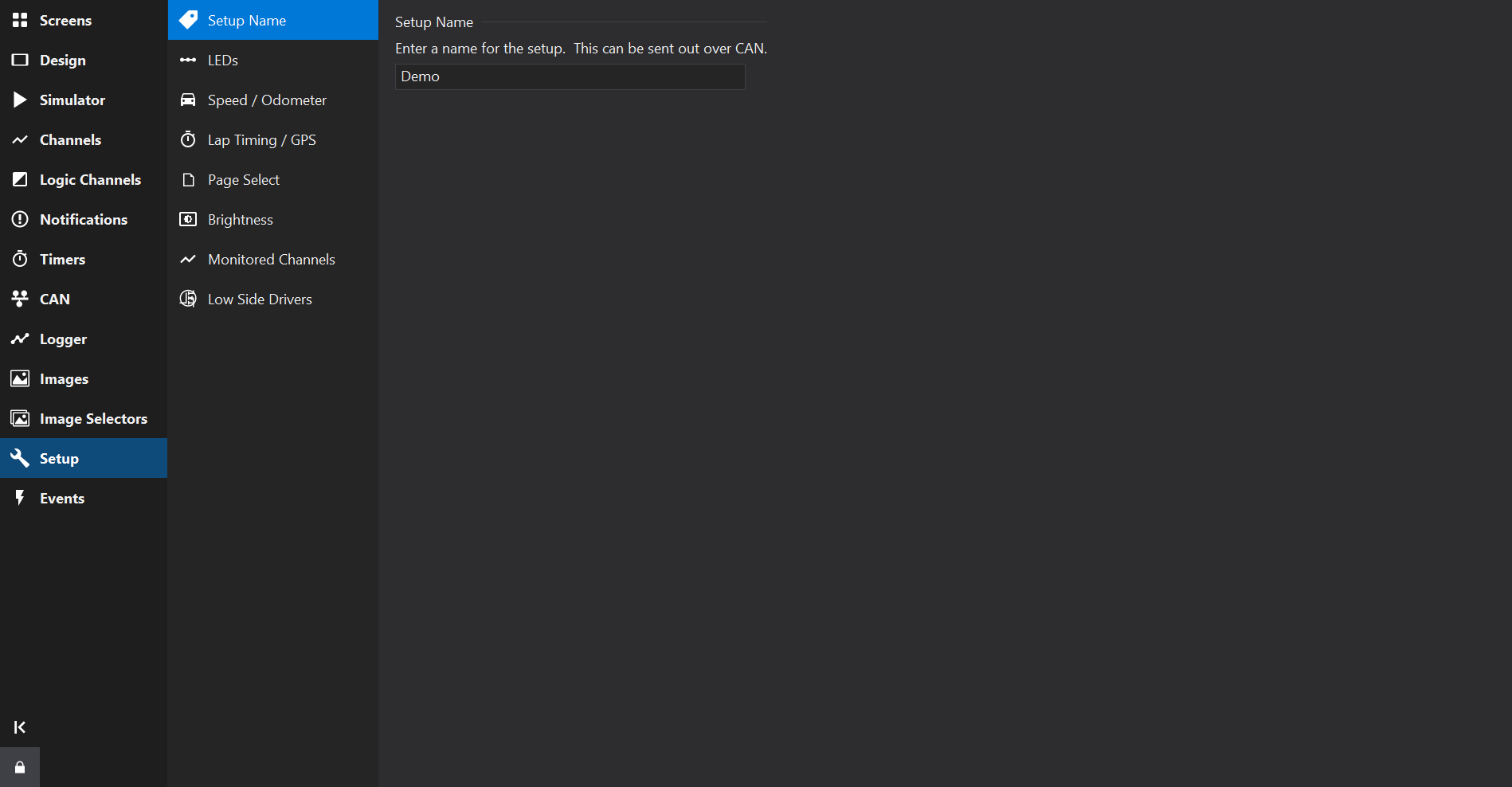
The Setup Name allows a name for the setup file to be defined.
This name may be displayed in Gauges using the Setup Name special format, vz.
Additionally the setup name may be transmitted over CAN. See CAN Transmit .
LED setup varies between display types. Some displays only support rule-based configuration: LEDs (Rule Based) .
Other displays support a simpler channel-per-LED configuration.
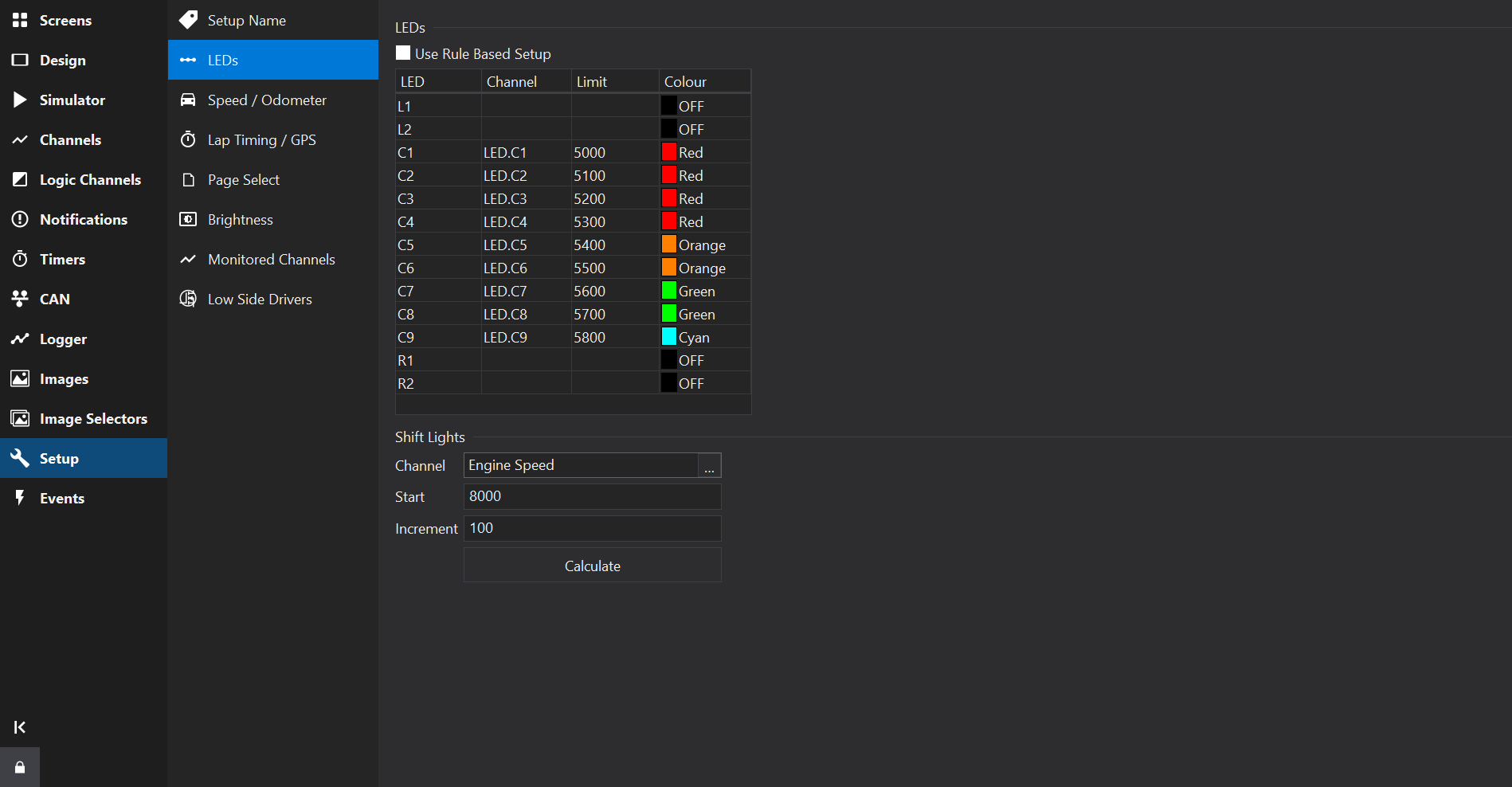
If available for the current display type, checking the Use Rule Based Setup allows complex LED patterns and rules to be specified.
See LEDs (Rule Based) for more details.
The LED List displays a fixed list of the LEDs available on the display.
Channels may be used to drive the LED, optionally with a limit and a colour.
For some displays, a flash channel may also be specified per LED (on/off). If activated, the LED will flash at the rate configured for the gauge as a whole.
Channels may be used to select the colour of an LED. The colour selected by the channel value depends on the display type, but for current displays the following table is used:
| Value | Colour |
|---|---|
| 0 | Off |
| 1 | Red |
| 2 | Green |
| 3 | Blue |
| 4 | Orange |
| 5 | Magenta |
| 6 | Yellow |
| 7 | Cyan |
| 8 | White |
| 9 | Channel (Direct Drive) |
| 10 | Channel RGB111 (Direct Drive) |
The RGB111 colour space is a 3-bit colour space with 1 bit per colour channel (Red, Green, Blue), meaning that input channels have a different colour mapping and should be in the range 0-7.
Depending upon the display type, a shift light pattern may be generated.
To generate a typical shift light pattern, set a Channel, a Start value and an Increment value and then click the Calculate button to generate the pattern.
Rule based LED setups enable different LED configurations on different pages and complex LED patterns based upon a collection of rules.
Groups of rules may be defined that are active on a selection of pages.
Rules consist of an arbitrary list of conditions that each produce a pattern.
If multiple rules are active at the same time then they can be prioritised.
Active rules at the same priority level can be cycled through at an adjustable rate.
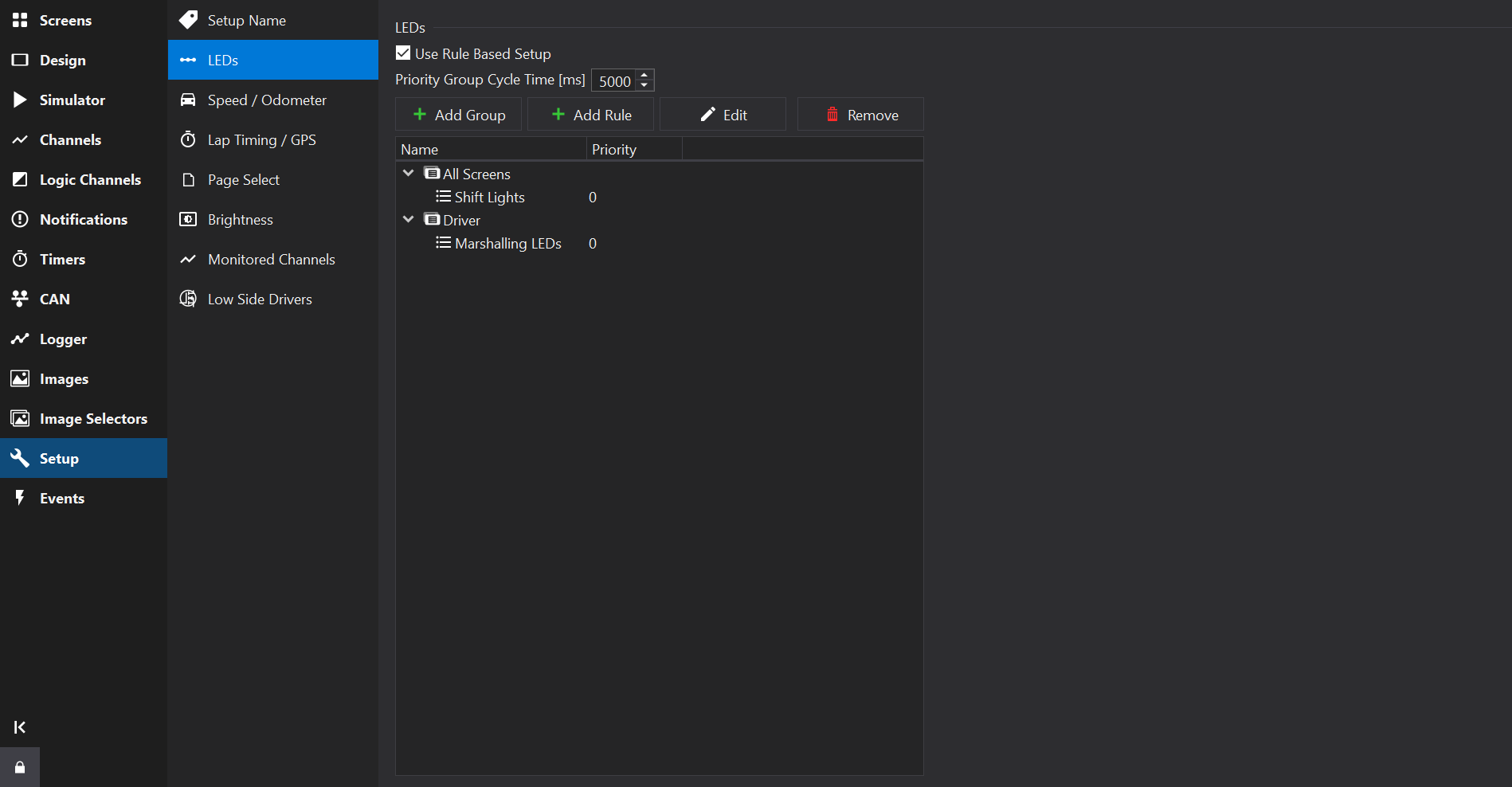
The main view shows a tree of groups and conditions; groups and rules are added and removed here.
Use the  Add Group to add a group.
Use the Add Rule to add a rule to the selected Group.
Use the  Delete button to remove selected groups / rules. The All Screens Group may not be deleted.
Use the  Edit button to edit the selected group or rule.
Rules and groups may be moved using drag & drop.
Use the context menu (right-click) to duplicate existing rules.
The Priority Group Cycle Time sets the time period at which multiple active rules of the same priority level are switched between.
Active rules at a lower priority level than another active rule may still have some effect if the active rule has not masked LEDs used in the lower priority rule. See LED Mask.
Rules within a group are only processed when the screen(s) it is assigned to are shown.
There is a default pre-defined group ‘All Screens’ which is active on every screen.
Named groups may be added and assigned to a selection of screens.
For example, you may add ‘Driver’ and ‘Diagnostic’ groups and only activate these on screens used by drivers or mechanics, respectively.
Use the Edit button to edit the selected group:

LED Group Editor
Sets the name of the group to express its intent or the set of screens it is associated with (e.g. “Driver” or “Diagnostic”).
A list of screens is presented for which the group will be enabled.
Screens may be selected using the Edit button on the LED Group Editor.
Rules may be added to Groups and can be given names to express their intent (e.g. Shift Lights / Critical Fault).
Use the Edit button to edit the selected rule:

LED Rule Editor
Rules have an LED Mask. When a rule is active, the LED mask prevents any lower-priority rules from modifying the state of the LEDs that are set in the mask. In general it is best to set the mask to cover all the LEDs used by the various patterns in the rule. The mask may also cover unused LEDs that should not be lit by lower priority rules.
Higher priority numbers indicate a higher processing priority and are processed first by the display.
If multiple rules are active at a given priority level then the display will cycle through those rules at the rate specified by the Priority Group Cycle Time setting on the Main View.
Rules may contain multiple logical conditions that can each activate a different LED pattern (LED states). The conditions are processed in order, with subsequent conditions (if active) overwriting any LED states from the prior condition.
If any conditions are active within a rule, then the rule is considered ‘active’.
To the right of the conditions list are the condition properties.
If multiple conditions are selected then the properties will act upon all of them.
Conditions may specify up to 2 channel comparisons, linked by a logical operator. If no comparators are selected then the condition is always active.
If a logical operator is not specified then only ‘Comparator A’ (if any) is evaluated.
Defines an LED pattern to display when a condition is active.
Click the … button on the LED Pattern Picker to open the pattern editor:

LED Pattern Picker

LED Pattern Editor
The LED Pattern Editor lists all LEDs available for configuration.
A fixed colour may be selected for each LED. Alternatively if a ‘Colour Channel’ is selected then the colour may be controlled by the channel value.
If a flash rate is configured then the LED will alternate between ‘Colour’ (or Channel based colour) and ‘Flash Colour’ at the given rate.
Selecting multiple LEDs allows their properties to be set collectively.
If the Pattern Mode property is set to Interpolate for a LED condition, then a channel may be selected to interpolate the state of LEDs in the selected pattern. This can be used to create shift light patterns without manually entering multiple conditions, which would otherwise be a time consuming process for a common use-case.
Interpolation only occurs over LEDs that are not configured in the pattern (i.e. have their colour set to ‘OFF’ and do not have a Colour Channel).
‘Right to Left’ will cause interpolated patterns to start from the right hand side as the starting point.
‘From’ and ‘To’ define the input channel value that signifies the beginning and ending of the interpolation range for the input channel. When the input channel is equal to the lower limit then no LEDs in the pattern will be shown. When the input channel reaches the ‘To’ value then all LEDs will be shown in the pattern.
‘From’ and ‘To’ may be reversed where To > From, in which case more LEDs will be shown as the input value decreases.
Interpolation may be used in conjunction with conditions.
If the Pattern Mode property is set to Bit Pattern for a LED condition, then a channel may be selected who’s individual bits correspond to LEDs.
Each bit in the input channel will correspond to LEDs that have been assigned a colour in the LEDs property. The first LED with a colour (i.e. not set to OFF) will be bit 0 and the next enabled LED will be bit 1 etc.
‘Right to Left’ will cause bit patterns to start from the right hand side; thr right-most LED that has a colour defined will correspond to (bit 0) in the input channel.
Dash Design will create hidden Bitmask Channel s to drive each LED individually.
The input channel will be converted to an integer representation prior to masking; the display uses 64bit floating point for channel values internally, giving exact conversions for up to 52 bits.
Channels may be used to select the colour of an LED. The colour selected by the channel value depends on the display type, but for current displays the following table is used:
| Value | Colour |
|---|---|
| 0 | Off |
| 1 | Red |
| 2 | Green |
| 3 | Blue |
| 4 | Orange |
| 5 | Magenta |
| 6 | Yellow |
| 7 | Cyan |
| 8 | White |
| 9 | Channel (Direct Drive) |
| 10 | Channel RGB111 (Direct Drive) |
The RGB111 colour space is a 3-bit colour space with 1 bit per colour channel (Red, Green, Blue), meaning that input channels have a different colour mapping and should be in the range 0-7.
The Speed / Odometer Tab provides configuration of a common Speed Input channel and the built-in Odometer function, along with trip setup features.
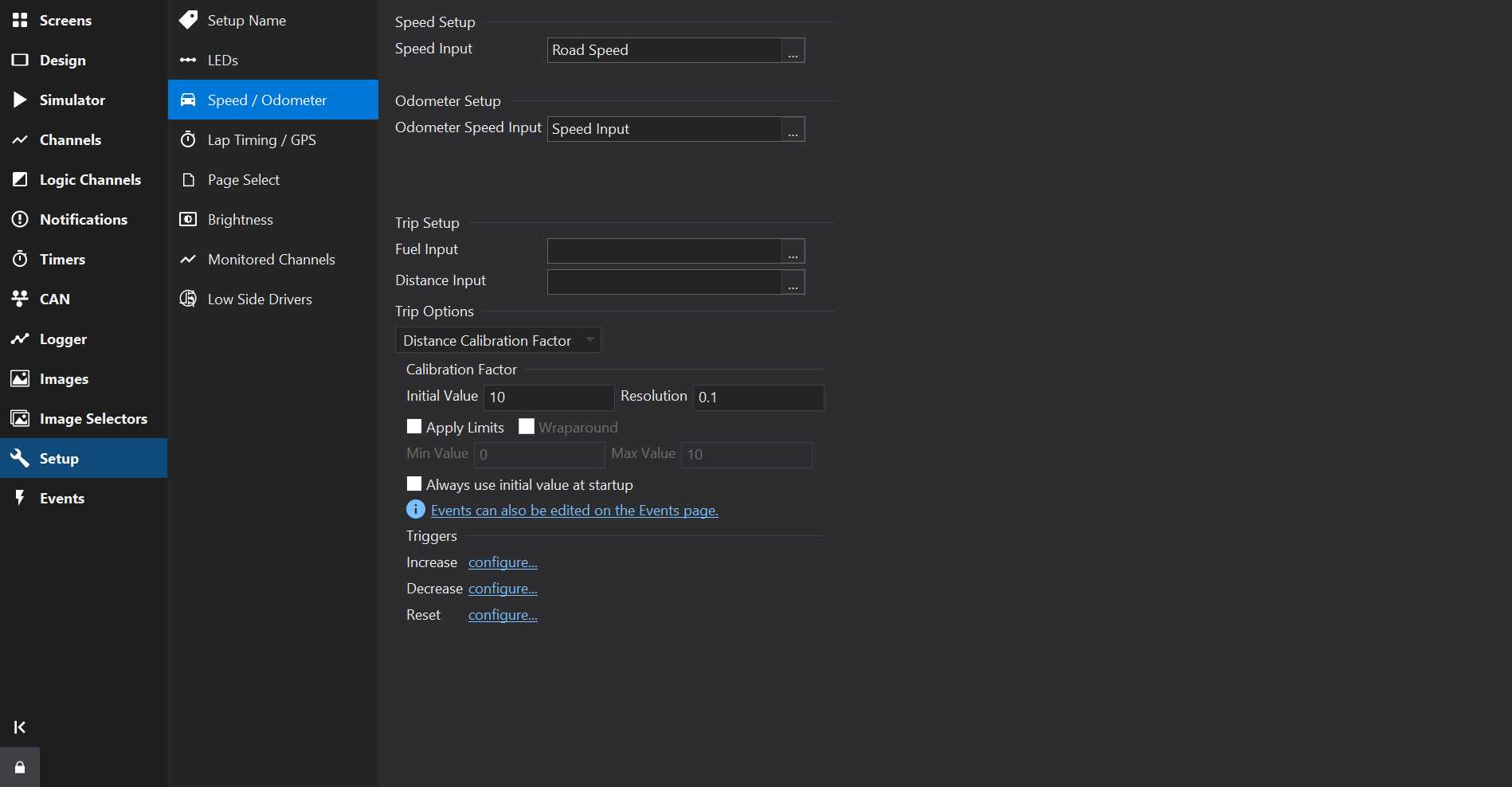
Select an input for the Speed Input channel. The Speed Input channel will output the same units of its input channel.
The vehicle speed is typically used in a number of places in display setups and Speed Input offers a single place to define the speed channel.
The channel being input to Speed Input is required to specify a speed unit so that correct physical unit conversions can be applied where needed.
If there is a misconfiguration here then the Setup Checker will issue a warning.
e.g.
 Error: Speed Input source ‘Road Speed’ does not have units of speed.
The Odometer is an internal counter backed up to non-volatile memory that cannot be reset. It is set to zero when the unit is built.
Select an output that is road speed and has units of speed. Typically the predefined “Speed Input” channel will be used here and will be set by default.
The software will arrange to convert units to [km/s] for correct functioning of the odometer.
An predefined Odometer channel will be available which is scaled in km and can be displayed on the screen.
Predefined trip related settings may be configured here.
Fuel Input defines the input used to calculate total fuel, trip fuel and fuel used. The fuel input can either be a Fuel Level input (which decrements as fuel is used) or a Fuel Used input (which increments as the fuel is used).
Distance Input defines the input used to calculate trip distance and countdown distance. This should be in either km or miles.
Select a trip counter to configure from the drop-down box. The trip counters are all configured to use the common Fuel Input and Distance Input channels, where appropriate.
Distance Calibration Factor defines the initial value of the distance calibration factor. All ‘co-driver’ distances are multiplied by the calibration before being displayed.
See also Calibration Factor Channel .
Countdown Distance Trip defines the initial and reset values of the countdown trip. See also Distance Countdown Channel .
Resolution defines the display resolution of these trip meters. See also Distance Trip Channel .
Configure the fuel trip meters as-per Fuel Channel
Specify the initial (and reset) values for the countdown timer.
Also specify the amount the timer is incremented and decremented by during increment/ decrement events by setting the Delta value in seconds.
The events for controlling the Countdown Timer may be specified here.
See also Timers Tab .
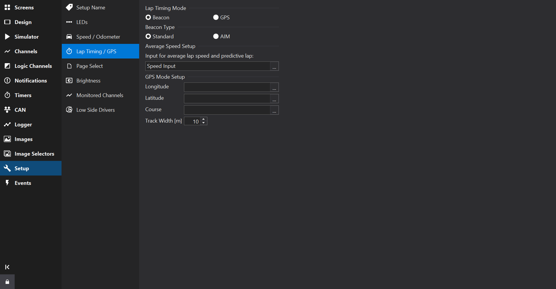
The Lap Timing / GPS Tab provides configuration of lap timing.
Several pre-defined channels are automatically created if the Display Module supports lap timing. See Lap Timing Channels .
In this mode, the beacon input is connected to a lap timing beacon receiver.
The lap timing outputs are updated as appropriate every time the beacon input is driven low.
If using an AIM beacon receiver, select AIM under Beacon Type.
AIM beacons have a slightly different output to other beacons; 3 pulses within 10ms must be received by the Display Module to register a beacon event.
Select a vehicle speed here. This will be set to the predefined Speed Input channel by default. Speed Input offers a single place to identify the speed channel and may be configured on the Speed / Odometer / Trip Setup page.
Use Speed Input here and set a common speed channel on the Speed / Odometer / Trip Setup page.
In this mode, a button (to ground) is connected to the beacon input.
Pressing the button (i.e. grounding the beacon input) for at least 500ms sets the location of the GPS Start/Finish line at the point the button was initially pressed, provided valid GPS data is being received by the display.
When the finish line is crossed again with the GPS Course within 90 degrees of the start finish line, a new lap is triggered.
For GPS mode to work, the outputs for GPS Longitude, GPS Latitude and GPS Course (all in degrees) must be specified together with the width of the track in metres. This should normally be a couple of metres wider than the actual track.
If using the serial input for GPS, these entries will be automatically populated.
The GPS Start/Finish position is stored between sessions and only changed when setting a new start/finish line.
Uploading a setup or uploading new firmware will reset the start/finish line.
If a speed input is specified, the average lap speed and predictive lap timing outputs will function.
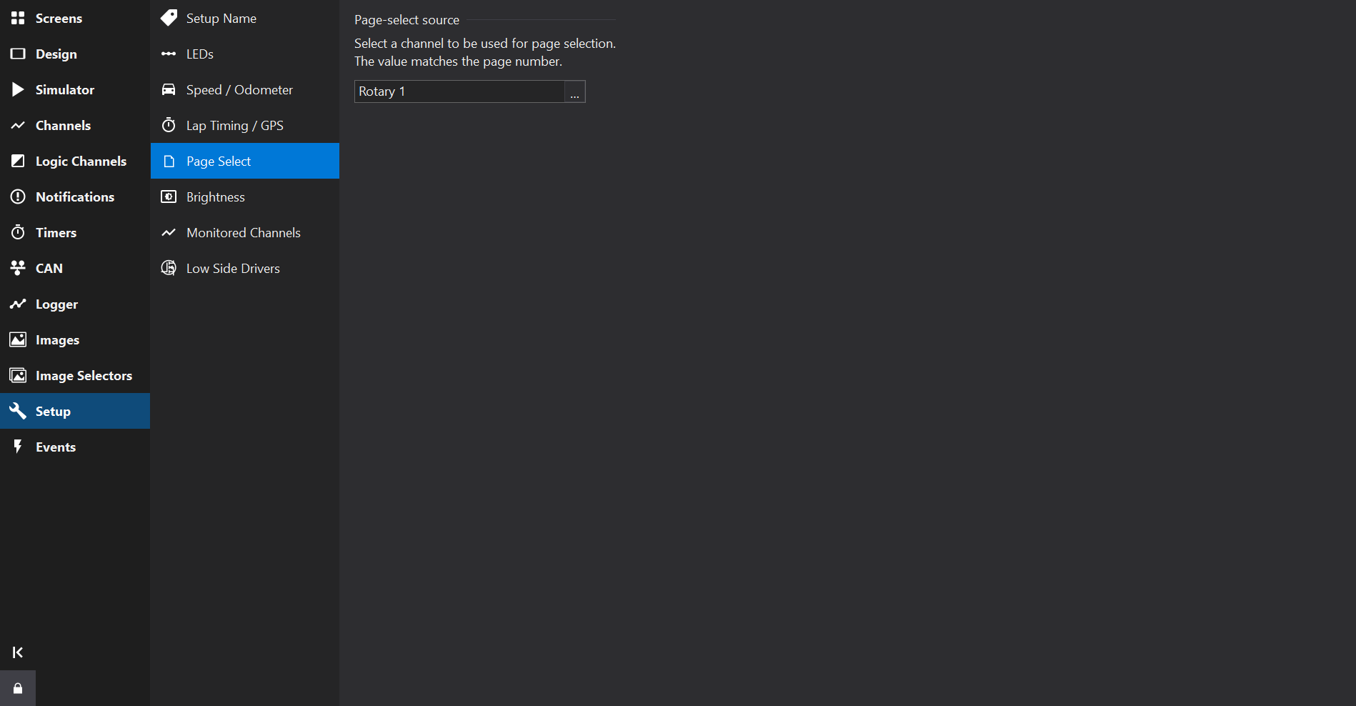
The Page Select Tab allows a channel to be selected to change the current screen (page).
Pages are numbered starting at 1 for the first page.
The Brightness Tab allows selection of a channel for controlling the screen brightness.
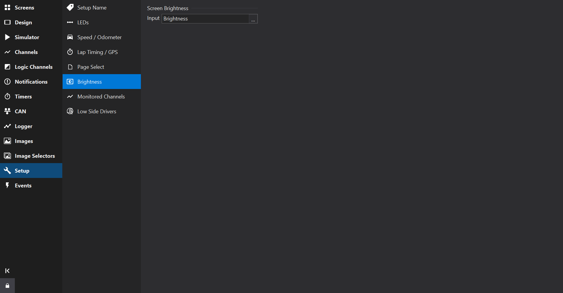
The display brightness can either be set coarsely or finely.
In either mode, the channel could be connected to one of the analogue inputs for example to use a rotary pot to control the brightness or it could be controlled from an ECU via the CAN bus.
The coarse control has eight brightness levels which can be selected by configuring a channel to produce a value in the range 0…7, with 7 being brightest. This mode is adequate for single seater/ steering wheel use where the display will be used in daylight conditions.
Brightness levels 6 and 7 of the coarse mode brightness are over-driven for extra brightness but this results in a loss of image contrast.
The fine control has 63 brightness levels which can be selected by configuring a channel to produce a value in the range 129…191 with 129 being the darkest, 191 the brightest and 160 the default brightness value.
If a fixed brightness is required, create a maths output whose equation is the brightness number required and use this as the brightness output.
The Monitored Channels lists channels that should be processed even when not being used by any gauges on the current page.
Some special channels such as Calibration Factor Channel can be added to the monitor channels list to ensure that it is persisted during power-off of the display.
Normally a given output is only monitored if used by a gauge on the currently displayed screen. In certain circumstances however, it is necessary to monitor some outputs irrespective of whether or not they are used by the currently displayed screen page.
For example, if the maximum coolant temperature is used only by gauges (or derived outputs), switching screens deletes the output as the screen changes and recreates it if necessary. The maximum output is then be reset and its’ information is lost. By adding this output to the Monitored Channels it is created when the display module is switched on. Changing screens has no effect on the output and the data is not reset unless a reset signal is received.
Furthermore, outputs added to the Monitored Channels are automatically stored in non-volatile memory. The values of a min, max or average output added to the Monitored Channels are preserved even when the screen is powered off. Consequently, it is important to make sure a reset method is set for such channels added to the Monitored Channels.
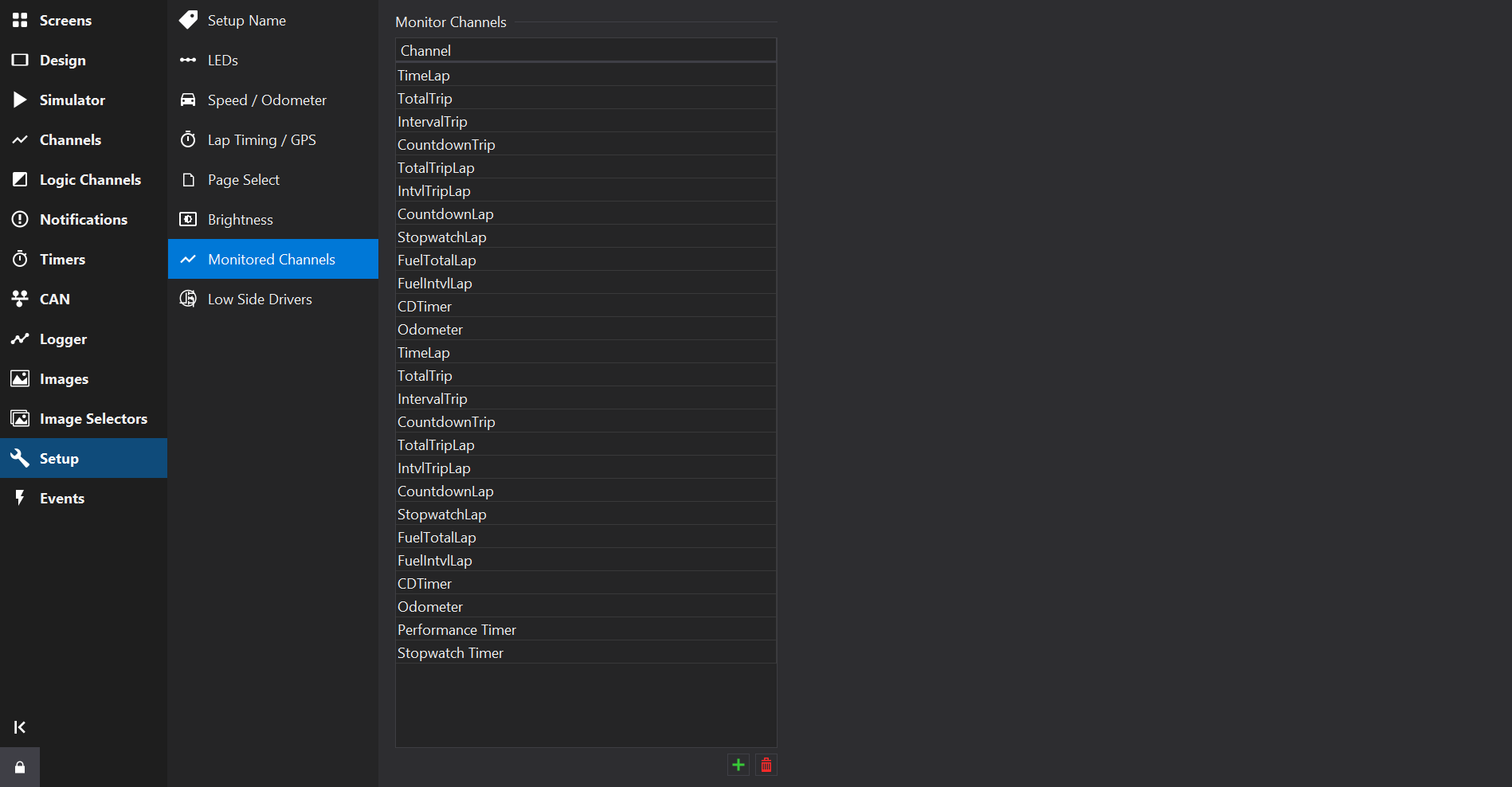
Use the and buttons to the bottom right of the channel list to add or remove. Predefined channels may not be removed.
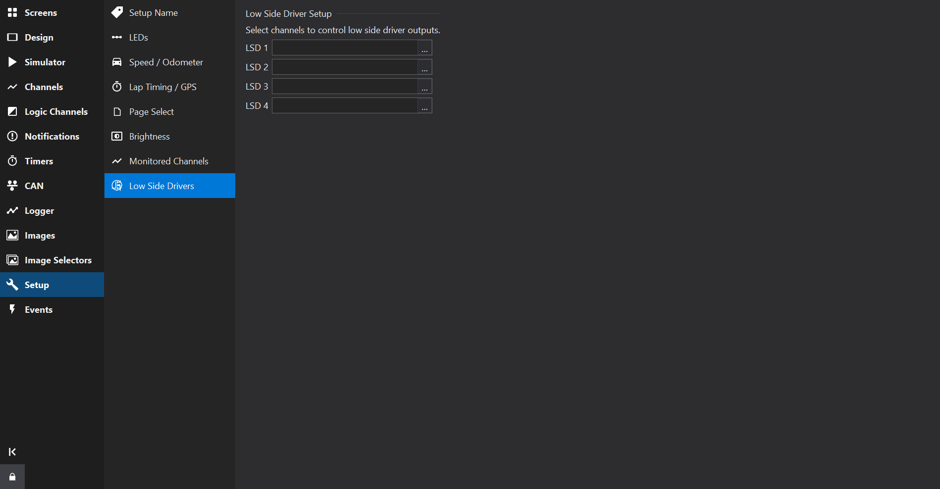
The Low Side Drivers Tab allows configuration of electrical outputs from the display module.
Low side drivers (switched to ground) can be used to drive relays or other items that are connected to a positive supply.
Select an output to drive each low side driver available on the display - when the output is greater than zero, the output will be on.