ECU

Overview

ECUs can be monitored and calibrated in real-time by connecting the ECU to the PC.

GWv4 supports both GEMS ECUs and ASAM Standard XCP based ECUs on a variety of transport layers including RS232, USB, CAN and Ethernet.

This chapter details the ECU connection process.

Please be aware that GEMS has two types of ECU, a standard, and a Simulink/Matlab enabled ECU (the EM80-M). Some of the processes for the EM80-M are slightly different, and you will find these details highlighted in the relevant places, e.g. ECU Internal Logging and EM80-M Internal logging have separate sections in this manual.

Subsections of ECU

ECU Definition Files

Overview

ECU Definition Files describe the memory layout of the ECU so that GWv4 can present the information stored in the ECU in a logical way and display/edit values using physical units such as Celsius or Fahrenheit rather then the internal representation used by the ECU.

Before you can connect to an ECU or edit Calibration Files, an ECU Definition File for the ECU will therefore need to be installed into GWv4.

Installation

There are a few ways to install ECU Definition Files:

  1. Drag & Drop your ECU Definition file onto GWv4 to install it.
  2. Open a Calibration or attempt to connect to an ECU. GWv4 will guide you through the process of locating an ECU definition file.
  3. Use the ECU Installations dialog. From the main menu go to Installations... and click the ‘Install…’ button.

The installation process archives ECU Definition files to an installation folder in the ProgramData folder in the EcuDef format.

ECU Definition File Formats

  • GIN (*.gin) - GEMS Proprietary ECU Definition file.
  • A2L (*.a2l) - ASAM Standard ECU Definition file. Requires an XCP License. A2L files have the file extension “.a2l”.
  • EcuDef (*.ecudef)- Compressed archive that, amongst other things, contains either a GIN file or an A2L file. EcuDef files take up considerably less disk space than GIN or A2L files. EcuDef files can also contain other supporting files.
Tip

If you do not have an ECU Definition file for your ECU, in most cases you can download them (gems.co.uk/downloads). Alternatively, contact GEMS.

ECU Connection

Working on tractive systems (which includes but is not limited to engine(s), motor(s), inverter(s), high voltage battery packs and high voltage cables) requires special experience and training.

Incorrect installation or use of GEMS Electronic Control units (ECUs) or software may lead to electrical / mechanical damage, injury or even death. As such, installation must only be performed by users with experience with electronic control systems and a competence of Windows based computer software.

All accompanying documentation must be read thoroughly before installation is attempted.

If you are in any doubts regarding the fitting and use of this product, please contact your reseller or GEMS directly at tech.support@gems.co.uk

General Engine Management Systems (GEMS) Ltd shall not be held responsible for any mechanical or electrical damage or personal injury occurring whilst using this product. Neither shall GEMS be held responsible for damage, injury or death caused by the misuse, misunderstanding or miscalibration of this product.

Overview

Connecting the PC to the ECU using a communications link is referred to as ‘going online’. Once online, calibration data is automatically downloaded from the ECU if necessary and channel data can be viewed. Some GWv4 functions, such as PC logging and auto mapping, can only be used when online.

If you are connecting to an ECU for the first time then you will need to adjust your connection settings. USB and Ethernet ECUs may be automatically detected and a notification will pop up in the bottom-right of the application window. This notification will contain a link to connect to the product and will automatically configure your communications settings.

If your ECU uses a different connection port from the previous port used (e.g. you are connecting via a direct USB connection instead of a serial cable) then you will also need to adjust your connection settings.

If you are having connection problems not covered by this topic, see Connection Troubleshooting.

Establishing a Connection

  • Connect the communications cable between the PC and the ECU.
  • Check that the correct port is selected in Connection Settings.
  • Click Connect Icon on the tool bar or select
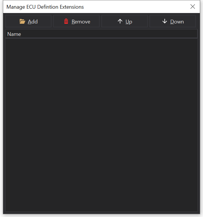
 ConnectShift+F7 from the main menu.

Alternatively you can choose to upload a calibration which will connect to the ECU then upload the calibration to it. To do this, select Send Calibration to ECU... or Send Current Calibration from the main menu.

If you choose just to connect, the calibration that is stored in the ECU will be downloaded and displayed.

For ECUs using serial connections that support Telemetry Stream mode, generally it is best to click on ConnectShift+F7 before supplying power to the ECU to avoid connection failures due to the ECU entering telemetry mode.

If you are connecting to your ECU using a serial connection, GWv4 can detect the Baud Rate by clicking on the ‘Detect Rate’ button. If you know the baud rate for your ECU then you can use “Set Rate” to configure it manually.

When you are online this will be displayed in the status bar at the bottom right of the GWv4 application window.

You will notice that when GWv4 is connecting the ECU Status window will be shown. This will show information about communication operations that are being performed between the PC and the ECU. This can be useful for diagnosing connection problems.

Once connected, GWv4 will load the ECU definition file for the connected ECU.

If an GIN file has not yet been installed for your ECU then a search will be performed.

This will search the GWv4 definitions folder for any ECU Definition files shipped with GWv4.

If a suitable ECU Definition file cannot be found then you will be offered to walk through the process of installing one. ECU Definition files can be downloaded from the GEMS website.

Connection Problems

If you are having problems connecting to your ECU, see Connection Troubleshooting.

ECU Definition Extension Files

Overview

ECU Definition Extension (EDX) Files augment ECU Definition Files with additional information that may not be possible to describe in the ECU Definition File itself.

For example, some features such as the ECU pinout / connector diagram is not possible to express in a standard A2L file. There may be other features that are not easy to add to A2L files if they are being generated from a tool.

Format

ECU Definition Extension Files have the file extension “gemsedx”. They are in an extended JSON (structured text) format that can be easily read and edited by humans, checked into source control tools and easily compared.

Installation

For ECU definition file authors with access to the ‘ginpkg’ tool, EDX files may be embedded in an ECU Definition File archive for automatic loading and installation.

Default EDX files may also be installed on disk in either the %PROGRAMDATA%/GEMS/GWv4/edx or %APPDATA%/GEMS/GWv4/edx directories. The edx file should be given the same name as the ECU, with or without the version as it appears in the ECU Installations dialog, accessible via the action Installations....

e.g. possible file names:

  • %PROGRAMDATA%/GEMS/GWv4/edx/DEMO.gemsedx
  • %APPDATA%/GEMS/GWv4/edx/DEMO-01X01.gemsedx

EDX files will only be loaded from these locations if the ECU Definition File does not already embed one.

Only 1 EDX file will be loaded from disk, in order of preference:

  1. %APPDATA%, with full version name (e.g. DEMO-01X01)
  2. %APPDATA%, name without version (e.g. DEMO)
  3. %PROGRAMDATA%, with full version name (e.g. DEMO-01X01)
  4. %PROGRAMDATA%, name without version (e.g. DEMO)

Inheritance

ECU Definition Files may embed multiple EDX files, which will be loaded in the order they are embedded. This allows for a base EDX file to be embedded in a common ECU Definition File, with additional EDX files for specific variants or versions. EDX files will be merged based upon elements with unique keys or appended to existing lists.

If EDX files are embedded into the calibration file, they will be loaded in the order they are embedded, after any EDX files embedded in the ECU Definition File or from disk default. This allows calibrations files to override things like wire colours for connector pins on the pinout diagram.

Embedding EDX Files in the Calibration File

EDX files may be embedded / removed / re-prioritized in the calibration file, using the ECU Definition Extensions… action:

ECU Definition Extensions Manager ECU Definition Extensions Manager

Name Pattern Matching

For some elements in the EDX file, name pattern matching is possible (e.g. to identify options that are an output pin number and should offer an alternative selector in the application UI).

Possible Wildcard patterns:

  • $N: any decimal number of any length.
  • $*: 0 or more characters of any length.
  • $+: 1 or more characters of any length.
  • $?: any single character.
  • $$: match a literal ‘$’.

Name matching is case insensitive and will also check ‘old names’ if they are present in the ECU Definition File; some items may be renamed in new versions of the ECU Definition File, with a record of their prior name.

Note also that for items that are matched for things like output pin numbers, any aliased items will also be considered a match.

For example, the option option iconOut Oil Feed 1 may be aliased with the option option iconOil Feed 1 Out. If the EDX file contains a rule that matches option iconOut Oil Feed 1, then option iconOil Feed 1 Out would also be matched.

Using wildcard matches simplifies maintenance of EDX files when the ECU Definition File is updated if naming conventions are consistent.

Name pattern exclusions are also possible. For example, consider the following:

{
    // This clause will match all options starting with the string "Out ", 
    // followed by any sequence of characters.  
    //
    // For this ECU, this would also match PWM module outputs (which are NOT output pin numbers).
    // These items are excluded by the "out_pin_options_exclude" clause below.
    "out_pin_options": [
        "Out $*", 
    ],
    // Exclude specific PWM module outputs that are not output pin numbers but would
    // otherwise match the "Out $*" clause above:
    "out_pin_options_exclude": [
        "Out $* PWM",
        "Out $* PWM$N", // e.g. exclude Out Idle PWM1
        "Out $* PWM#$N", // e.g. exclude Out VVC#1 PWM#1
    ],
}

Formulas

Formulas can be used in a number of places. These follow A2L formula rules with some additional extensions.

A2L formulas closely follow C expressions and use the same operator precedence.

<% vendor %> Extensions

Extension Purpose
Relational operators ( ==, !=, <, <=, >, >= ) Compare two values, resulting in 0 or 1.
Ternary operator a ? b : c If ‘a’ is true the ‘b’ is executed, otherwise ‘c’ is executed.
arg(i) function Selects input argument ‘i’ (zero based) from input arguents list. Can be used for selectors.
option(name) function Select an option object by name.
table(name) function Select a table object by name.
map(name) function Select a map object by name.
channel(name) function Select a channel object by name.

Example EDX File

In future a JSON schema will be developed for easier editing in tools that support JSON schema validation.

For the time being, the following is an example EDX file that describes a connector with multiple sections, each with multiple pins, some of which have specific functions and conditions for use.

There are also some examples of wire colours and patterns that may be used in the connector diagram.

Also, output pins / switch inputs / A2Ds etc may be identified.

Note that an extended (JSONX) format is used so that comments are allowed and additionally some relaxations to the strict JSON format are allowed (e.g. trailing commas / missing commas, unquoted keys etc).

For the purpose of integration with external tools it is generally recommended to stick to strict JSON format where possible.

Editors such as Visual Studio Code can be extended to support the ‘jsonc’ format (JSON with comments) which is a good compromise.

// Comments may be included in EDX files.
{
    "ecu_family": [
        "DEMO"
    ],

    // Default shape / size for pins in the connector diagram:
    "default_pin": {
        "shape": "circle",
        "size": [2,2]
    },

    // Describe the ECU connectors and any predefined functions.
    "connectors": [
        {
            "id": "AB",
            "part": "6437288-3",
            "comment": "Mates with: 3-1437290-7 (26P), 4-1437290-0 (34P)",
            "pos": [50, 0],
            "size": [75, 24.6],
            "sections": [
                {
                    "id": "A",
                    "pos": [0, 0],
                    "pin_offset": [6.2, 6.2],
                    "size": [38.4, 24.6],
                    "diagram": [
                        {
                            "shape": "round_rect",
                            "radius": 2,
                            "pos": [5, 5],
                            "size": [28.4, 14.6],
                        },
                        {
                            "shape": "round_rect",
                            "radius": 6,
                            "pos": [1, 1],
                            "size": [36.4, 22.6],
                        },
                        {
                            "shape": "round_rect",
                            "radius": 7,
                            "pos": [0, 0],
                            "size": [38.4, 24.6],
                        },
                    ],
                    "pins": [
                        // row 1, 9 pins, pitch 3mm
                        {
                            "id": "A1",
                            "func": "BRGB2",
                            "dir": "O", // I / O / IO
                            "out_pin": 9,
                            "pwm": 2,
                            "throttle": 2,
                            "pos": [0, 0], // x,y position on connector diagram
                            "wire": {
                                "colour": ["#FF0000","#00DD00"], // Colour(s) of the wire, some may be striped with multiple colours.  Could be a single colour with no array.
                                "width": [1, 1], // Width of the stripes (optional)
                                "pattern": "D", // D: diagonal, T: transverse, L: longitudinal (optional)
                                "text": "Red/Green"
                            },
                            "comment": "Act Throttle 2",
                            "used_if": [ // Conditions that lead to this output being used (overrides / conflicts with use of out_pin)
                                {
                                    "func": "Act Throttle 2",
                                    "expr": "option('BridgeB Enable') && option('Act Throttle 2') && !option('Act T 2 No Drive')",
                                }
                            ]
                        },
                        {
                            "id": "A2",
                            "func": "BRGB1",
                            "dir": "O", // I / O / IO
                            "out_pin": 8,
                            "pwm": 1,
                            "throttle": 2,
                            "pos": [3, 0], // x,y position on connector diagram
                            "wire": {
                                "colour": ["#00DD00","#3333DD"], // Colour(s) of the wire, some may be striped with multiple colours.  Could be a single colour with no array.
                                "width": [1, 1], // Width of the stripes (optional)
                                "pattern": "T", // D: diagonal, T: transverse, L: longitudinal (optional)
                                "text": "Green/Blue"
                            },
                            "comment": "Act Throttle 2",
                            "used_if": [
                                {
                                    "func": "Act Throttle 2",
                                    "expr": "option('BridgeB Enable') && option('Act Throttle 2') && !option('Act T 2 No Drive')",
                                }
                            ]
                        },
                        {
                            "id": "A3",
                            "func": "IGSWT",
                            "a2d": 13,
                            "pos": [6, 0],
                            "comment": "5V to turn on MAIN RELAY",
                            "wire": {
                                "colour": ["#FFFFFF","#000000"], // Colour(s) of the wire, some may be striped with multiple colours.  Could be a single colour with no array.
                                "width": [1, 1], // Width of the stripes (optional)
                                "pattern": "line", // D: diagonal, T: transverse, L: longitudinal, line (optional)
                                "text": "White/Black"
                            },
                        },
                        {
                            "id": "A4",
                            "func": "Fuel8",
                            "out_pin": 24,
                            "pos": [9, 0],
                            "comment": "Fuel Injector 8",
                            "used_if": [
                                {
                                    "func": "Fuel 8",
                                    "expr": "option('Fuel 8')"
                                }
                            ]
                            "wire": {
                                "colour": ["#FF7F00","#000000"], // Colour(s) of the wire, some may be striped with multiple colours.  Could be a single colour with no array.
                                "width": [1, 1], // Width of the stripes (optional)
                                "pattern": "L", // D: diagonal, T: transverse, L: longitudinal (optional)
                                "text": "Orange/Black"
                            },
                        },
                        {
                            "id": "A5",
                            "func": "Fuel7",
                            "out_pin": 25,
                            "pos": [12, 0],
                            "comment": "Fuel Injector 7",
                            "used_if": [
                                {
                                    "func": "Fuel 7",
                                    "expr": "option('Fuel 7')"
                                }
                            ]
                        },
                        {
                            "id": "A6",
                            "func": "Fuel6",
                            "out_pin": 26,
                            "pos": [15, 0],
                            "comment": "Fuel Injector 6",
                            "used_if": [
                                {
                                    "func": "Fuel 6",
                                    "expr": "option('Fuel 6')"
                                }
                            ]
                        },
                        {
                            "id": "A7",
                            "func": "Fuel5",
                            "out_pin": 27,
                            "pos": [18, 0],
                            "comment": "Fuel Injector 5",
                            "used_if": [
                                {
                                    "func": "Fuel 5",
                                    "expr": "option('Fuel 5')"
                                }
                            ]
                        },
                        {
                            "id": "A8",
                            "func": "Fuel4",
                            "out_pin": 28,
                            "pos": [21, 0],
                            "comment": "Fuel Injector 4",
                            "used_if": [
                                {
                                    "func": "Fuel 4",
                                    "expr": "option('Fuel 4')"
                                }
                            ]
                        },
                        {
                            "id": "A9",
                            "func": "Fuel3",
                            "out_pin": 29,
                            "pos": [24, 0],
                            "comment": "Fuel Injector 3",
                            "used_if": [
                                {
                                    "func": "Fuel 3",
                                    "expr": "option('Fuel 3')"
                                }
                            ]
                        },
                        // Row 2, 8 pins
                        {
                            "id": "A10",
                            "func": "PWR",
                            "a2d": 14,
                            "pos": [1.5, 3.2],
                            "comment": "1st Power IN",
                        },
                        {
                            "id": "A11",
                            "func": "12VOUT",
                            "pos": [4.5, 3.2],
                            "comment": "12V Battery 100mA sensor supply"
                        },
                        {
                            "id": "A12",
                            "func": "IGN1",
                            "out_pin": 56,
                            "mux": "IGMUX11", // Multiplexor (used for ignition mux)
                            "pos": [7.5, 3.2],
                            "comment": "CoilA IGN1&3 TTL ignition multiplex",
                            "used_if": [ 
                                {
                                    "func": "Ign 1",
                                    "expr": "option('Ign 1')"
                                }
                            ]
                        },
                        {
                            "id": "A13",
                            "func": "IGN4",
                            "out_pin": 58,
                            "mux": "IGMUX21",
                            "pos": [10.5, 3.2],
                            "comment": "CoilB IGN2&4 TTL ignition multiplex",
                            "used_if": [ 
                                {
                                    "func": "Ign 4",
                                    "expr": "option('Ign 4')"
                                }
                            ]
                        },
                        {
                            "id": "A14",
                            "func": "IGN3",
                            "out_pin": 57,
                            "mux": "IGMUX12",
                            "pos": [13.5, 3.2],
                            "comment": "CoilA IGN1&3 TTL ignition multiplex",
                            "used_if": [
                                {
                                    "func": "Ign 3",
                                    "expr": "option('Ign 3')"
                                }
                            ]
                        },
                        {
                            "id": "A15",
                            "func": "IGN2",
                            "out_pin": 59,
                            "mux": "IGMUX22",
                            "pos": [16.5, 3.2],
                            "comment": "CoilB IGN2&4 TTL ignition multiplex",
                            "used_if": [
                                {
                                    "func": "Ign 2",
                                    "expr": "option('Ign 2')"
                                }
                            ]
                        },
                        {
                            "id": "A16",
                            "func": "IGN5",
                            "out_pin": 3,
                            "pos": [19.5, 3.2],
                            "comment": "TTL",
                            "used_if": [
                                {
                                    "func": "Ign 5",                                    
                                    "expr": "option('Ign 5')"
                                }
                            ]
                        },
                        {
                            "id": "A17",
                            "func": "IGN6",
                            "out_pin": 4,
                            "pos": [22.5, 3.2],
                            "comment": "TTL",
                            "used_if": [
                                {
                                    "func": "Ign 6",
                                    "expr": "option('Ign 6')"
                                }
                            ]
                        },
                        // Row 3, 8 pins
                        {
                            "id": "A18",
                            "func": "PWR2",
                            "a2d": 14,
                            "pos": [1.5, 7],
                            "comment": "2nd Power IN",                    
                        },
                        {
                            "id": "A19",
                            "func": "Crank",
                            "timer": 1,
                            "pos": [4.5, 7],
                            "pullup": "option('T1 Pull-Up') ? 1000 : 0",
                            "comment": "VR Filter"
                        },                
                        {
                            "id": "A20",
                            "func": "Cam",
                            "timer": 2,
                            "swt": 32,
                            "pos": [7.5, 7],
                            "pullup": "option('T2 Pull-Up') ? 1000 : 0",
                            "comment": "VR Filter"
                        },
                        {
                            "id": "A21",
                            "func": "T3",
                            "timer": 3,
                            "swt": 25,
                            "pos": [10.5, 7],
                            "pullup": "option('T3 Pull-Up') ? 1000 : 0",
                            "comment": "VR"
                        },
                        {
                            "id": "A22",
                            "func": "T4",
                            "timer": 4,
                            "swt": 26,
                            "pos": [13.5, 7],
                            "pullup": "option('T4 Pull-Up') ? 1000 : 0",
                            "comment": "VR"
                        },
                        {
                            "id": "A23",
                            "func": "T5",
                            "timer": 5,
                            "swt": 27,
                            "pos": [16.5, 7],
                            "pullup": "4700",
                        },
                        {
                            "id": "A24",
                            "func": "T7",
                            "timer": 7,
                            "swt": 29,
                            "pos": [19.5, 7],
                            "pullup": "4700",
                            "comment": "Logic only"
                        },
                        {
                            "id": "A25",
                            "func": "T8",
                            "timer": 8,
                            "swt": 30,
                            "pos": [22.5, 7],
                            "pullup": "4700",
                            "comment": "Logic only"
                        },
                        // row 4, 9 pins RTL, pitch 3mm
                        {
                            "id": "A26",
                            "func": "PGND2",
                            "pos": [0, 10.2],
                        },
                        {
                            "id": "A27",
                            "func": "CAN2L",
                            "pos": [3, 10.2],
                            "comment": "8TX",
                        },
                        {
                            "id": "A28",
                            "func": "CAN2H",
                            "pos": [6, 10.2],
                            "comment": "8TX",
                        },
                        {
                            "id": "A29",
                            "func": "TX",
                            "pos": [9, 10.2],
                            "comment": "Serial Comms Transmit (TTL)",
                        },
                        {
                            "id": "A30",
                            "func": "S5V2",
                            "pos": [12, 10.2],
                            "comment": "5V 100mA",
                        },
                        {
                            "id": "A31",
                            "func": "RX",
                            "pos": [15, 10.2],
                            "comment": "Serial Comms Receive (TTL)",
                        },
                        {
                            "id": "A32",
                            "func": "T9",
                            "timer": 9,
                            "swt": 9,
                            "pos": [18, 10.2],
                            "pullup": "4700",
                            "comment": "Logic only"
                        },
                        {
                            "id": "A33",
                            "func": "T10",
                            "timer": 10,
                            "swt": 10,
                            "pos": [21, 10.2],
                            "pullup": "4700",
                            "comment": "Logic only"
                        },
                        {
                            "id": "A34",
                            "func": "TGND",
                            "pos": [24, 10.2],
                            "comment": "signal 100mA"
                        },
                    ]
                },
                {
                    "id": "B",        
                    "pos": [40, 0],     
                    "pin_offset": [6.2, 6.2],
                    "size": [32.4, 24.6],
                    "diagram": [
                        {
                            "shape": "round_rect",
                            "radius": 2,
                            "pos": [5, 5],
                            "size": [22.4, 14.6],
                        },
                        {
                            "shape": "round_rect",
                            "radius": 6,
                            "pos": [1, 1],
                            "size": [30.4, 22.6],
                        },
                        {
                            "shape": "round_rect",
                            "radius": 7,
                            "pos": [0, 0],
                            "size": [32.4, 24.6],
                        },
                    ],        
                    // 26 pin connector 7,6,6,7
                    "pins":[
                        // Row 1, 7 pins
                        {
                            "id": "B1",
                            "func": "Fuel2",
                            "out_pin": 30,
                            "pos": [18, 0],
                            "comment": "Fuel Injector 2",
                            "used_if": [
                                {
                                    "func": "Fuel 2",
                                    "expr": "option('Fuel 2')"
                                }
                            ]
                        },
                        {
                            "id": "B2",
                            "func": "Fuel1",
                            "out_pin": 31,
                            "pos": [15, 0],
                            "comment": "Fuel Injector 1",
                            "used_if": [
                                {
                                    "func": "Fuel 1",
                                    "expr": "option('Fuel 1')"
                                }
                            ]
                        },
                        {
                            "id": "B3",
                            "func": "PWM3",                    
                            "pwm": 3,
                            "out_pin": 10,
                            "pos": [12, 0],
                        },
                        {
                            "id": "B4",
                            "func": "PWM4",
                            "pwm": 4,
                            "out_pin": 11,
                            "pos": [9, 0],                    
                        },
                        {
                            "id": "B5",
                            "func": "PWM7",
                            "pwm": 7,
                            "out_pin": 14,
                            "pos": [6, 0],
                        },
                        {
                            "id": "B6",
                            "func": "PWM8",
                            "pwm": 8,
                            "out_pin": 15,
                            "pos": [3, 0],
                        },
                        {
                            "id": "B7",
                            "func": "MAINRLY",
                            "pos": [0, 0],
                            "comment": "(IGNSWT)",
                        },
                        // Row 2, 6 pins
                        {
                            "id": "B8",
                            "func": "IGN7",
                            "out_pin": 5,
                            "pos": [16.5, 3.2],
                            "comment": "TTL",
                            "used_if": [
                                {
                                    "func": "Ign 7",
                                    "expr": "option('Ign 7')"
                                }
                            ]
                        },
                        {
                            "id": "B9",
                            "func": "IGN8",
                            "out_pin": 6,
                            "pos": [13.5, 3.2],
                            "comment": "TTL",
                            "used_if": [
                                {
                                    "func": "Ign 8",
                                    "expr": "option('Ign 8')"
                                }
                            ]
                        },
                        {
                            "id": "B10",
                            "func": "ACTTP1",
                            "a2d": 10,
                            "swt": 51,
                            "pos": [10.5, 3.2],
                            "pullup": "47000",
                            "comment": "Act Throttle 1 position 1st",
                            "channels":[
                                "Act T1 raw",
                                "Analog 10"
                            ],
                            "used_if": [
                                {
                                    "option": "Act T1 Active"
                                }
                            ]
                        },
                        {
                            "id": "B11",
                            "func": "ACTTP2",
                            "a2d": 9,
                            "swt": 50,
                            "pos": [7.5, 3.2],
                            "pullup": "47000",
                            "comment": "Act Throttle 1 position 2nd",
                            "channels":[
                                "Act T2 raw",
                                "Analog 09"
                            ],
                            "used_if": [
                                {
                                    "option": "Act T2 Active"
                                }
                            ]
                        },
                        {
                            "id": "B12",
                            "func": "ACTTP3",
                            "a2d": 18,
                            "swt": 59,
                            "pos": [4.5, 3.2],
                            "pullup": "47000",
                            "comment": "Act Throttle 2 position 1st",
                            "channels":[
                                "Act T3 raw",
                                "Analog 18"
                            ],
                            "used_if": [
                                {
                                    // Alternative to using an expression + a function name.
                                    "option": "Act T3 Active"
                                }
                            ]
                        },
                        {
                            "id": "B13",
                            "func": "ACTTP4",
                            "a2d": 19,
                            "swt": 60,
                            "pos": [1.5, 3.2],
                            "pullup": "47000",
                            "comment": "Act Throttle 2 position 2nd",
                            "channels":[
                                "Act T4 raw",
                                "Analog 19"
                            ],
                            "used_if": [
                                {
                                    "option": "Act T4 Active"
                                }
                            ]
                        },
                        // 3rd row, 6 pins
                        {
                            "id": "B14",
                            "func": "OXHEATB",
                            "out_pin": 33,
                            "pos": [16.5, 7],
                            "comment": "Lambda Sensor Heater B (white to gray)",
                        },
                        {
                            "id": "B15",
                            "func": "AGND2",
                            "pos": [13.5, 7],
                            "comment": "signal 100mA",
                        },
                        {
                            "id": "B16",
                            "func": "OXB1",
                            "pos": [10.5, 7],
                            "comment": "Yellow VM",
                        },
                        {
                            "id": "B17",
                            "func": "OXB2",
                            "a2d": 23,
                            "pos": [7.5, 7],
                            "comment": "Lambda, red APE IP",
                        },
                        {
                            "id": "B18",
                            "func": "OXB3",
                            "a2d": 20,
                            "pos": [4.5, 7],
                            "comment": "Ri, black UN RE",
                        },
                        {
                            "id": "B19",
                            "func": "OXB4",
                            "pos": [1.5, 7],
                            "comment": "Violet IA trim resistor",
                        },
                        // Row4, 7 pins
                        {
                            "id": "B20",
                            "func": "AGND3",
                            "pos": [18, 10.2],
                            "comment": "2R6",
                        },
                        {
                            "id": "B21",
                            "func": "S5V3",
                            "pos": [15, 10.2],
                            "comment": "5V 100mA",
                        },
                        {
                            "id": "B22",
                            "func": "T11",
                            "timer": 11,
                            "swt": 11,
                            "pos": [12, 10.2],
                            "pullup": "4700",
                            "comment": "Logic only"
                        },
                        {
                            "id": "B23",
                            "func": "T12",
                            "timer": 12,
                            "swt": 12,
                            "pos": [9, 10.2],
                            "pullup": "4700",
                            "comment": "Logic only"
                        },
                        {
                            "id": "B24",
                            "func": "KNOCKN",
                            "swt": 43,
                            "a2d": 2,
                            "pos": [6, 10.2],
                        },
                        {
                            "id": "B25",
                            "func": "KNOCKP",
                            "a2d": 2,
                            "pos": [3, 10.2],
                        },
                        {
                            "id": "B26",
                            "func": "PGND",
                            "pos": [0, 10.2],
                        }
                    ]
                }
            ]
        },
        {
            "id": "C",
            "part": "6437288-2",
            "comment": "Mates with: 4-1437290-1",
            "pos": [0, 0],
            "size": [38.4, 24.6],
            "sections": [
                {
                    "id": "C",
                    "pos": [0, 0],
                    "pin_offset": [6.2, 6.2],
                    "size": [38.4, 24.6],
                    "diagram": [
                        {
                            "shape": "round_rect",
                            "radius": 2,
                            "pos": [5, 5],
                            "size": [28.4, 14.6],
                        },
                        {
                            "shape": "round_rect",
                            "radius": 6,
                            "pos": [1, 1],
                            "size": [36.4, 22.6],
                        },
                        {
                            "shape": "round_rect",
                            "radius": 7,
                            "pos": [0, 0],
                            "size": [38.4, 24.6],
                        },
                    ],         
                    "pins":[
                        // row 1, 9 pins RTL, pitch 3mm
                        {
                            "id": "C1",
                            "func": "PWM10",
                            "pwm": 10,
                            "out_pin": 17,
                            "pos": [0, 0],
                            "comment": "No recirculation diode",
                        },
                        {
                            "id": "C2",
                            "func": "PWM11",
                            "pwm": 11,
                            "out_pin": 18,
                            "pos": [3, 0],
                            "comment": "No recirculation diode",
                        },
                        {
                            "id": "C3",
                            "func": "PWM12",
                            "pwm": 12,
                            "out_pin": 19,
                            "pos": [6, 0],
                            "comment": "No recirculation diode",
                        },
                        {
                            "id": "C4",
                            "func": "PWM13",
                            "pwm": 13,
                            "out_pin": 20,
                            "pos": [9, 0],                    
                        },
                        {
                            "id": "C5",
                            "func": "PWM14",
                            "pwm": 14,
                            "out_pin": 21,
                            "pos": [12, 0],
                        },
                        {
                            "id": "C6",
                            "func": "PWM15",
                            "pwm": 15,
                            "out_pin": 22,
                            "pos": [15, 0],
                        },
                        {
                            "id": "C7",
                            "func": "PWM16",
                            "pwm": 16,
                            "out_pin": 23,
                            "pos": [18, 0],                    
                        },
                        {
                            "id": "C8",
                            "func": "BRGA1",
                            "out_pin": 12,
                            "pwm": 5,
                            "throttle": 2,
                            "pos": [21, 0],
                            "comment": "Act Throttle 1",
                            "used_if": [ 
                                {
                                    "func": "Act Throttle 1",
                                    "expr": "option('BridgeA Enable') && option('Act Throttle 1') && !option('Act T 1 No Drive')",
                                }
                            ]
                        },
                        {
                            "id": "C9",
                            "func": "BRGA2",
                            "out_pin": 13,
                            "pwm": 6,
                            "throttle": 2,
                            "pos": [24, 0],
                            "comment": "Act Throttle 1",
                            "used_if": [
                                {
                                    "func": "Act Throttle 1",
                                    "expr": "option('BridgeA Enable') && option('Act Throttle 1') && !option('Act T 1 No Drive')",
                                }
                            ]
                        },
                        // row2, 8 pins, offset 1.5mm
                        {
                            "id": "C10",
                            "func": "PWM9",
                            "out_pin": 16,
                            "pwm": 9,
                            "pos": [1.5, 3.2],
                            "comment": "No recirculation diode",
                        },
                        {
                            "id": "C11",
                            "func": "ACCEL1",
                            "a2d": 7,
                            "swt": 48,
                            "pullup": 47000,
                            "pos": [4.5, 3.2],
                            "comment": "Pedal Position 1",
                            "used_if": [
                                {
                                    "option": "Pedal1 Active",
                                }
                            ]
                        },
                        {
                            "id": "C12",
                            "func": "ACCEL2",
                            "a2d": 6,
                            "swt": 47,
                            "pullup": 47000,
                            "pos": [7.5, 3.2],
                            "comment": "Pedal Position 2",
                            "used_if": [
                                {
                                    "option": "Pedal2 Active",
                                }
                            ]
                        },
                        {
                            "id": "C13",
                            "func": "AN15",
                            "a2d": 15,
                            "swt": 56,
                            "pullup": 4700,
                            "pos": [10.5, 3.2],
                        },
                        {
                            "id": "C14",
                            "func": "AN16",
                            "a2d": 16,
                            "swt": 57,
                            "pullup": 4700,
                            "pos": [13.5, 3.2],
                        },
                        {
                            "id": "C15",
                            "func": "AN17",
                            "a2d": 17,
                            "swt": 58,
                            "pullup": 4700,
                            "pos": [16.5, 3.2],
                        },
                        {
                            "id": "C16",
                            "func": "AIT",
                            "a2d": 8,
                            "swt": 49,
                            "pullup": 4700,
                            "pos": [19.5, 3.2],
                            "comment": "Air Intake Temperature",
                        },
                        {
                            "id": "C17",
                            "func": "CTEMP",
                            "a2d": 11,
                            "swt": 52,
                            "pullup": 2200,
                            "pos": [22.5, 3.2],
                            "comment": "Coolant Temperature",
                        },
                        // Row 3, 8 pins
                        {
                            "id": "C18",
                            "func": "OXHEATA",
                            "out_pin": 32,
                            "pos": [1.5, 7],
                            "comment": "Lambda Sensor Heater A",
                        },
                        {
                            "id": "C19",
                            "func": "OXA1",
                            "pos": [4.5, 7],
                            "comment": "Yellow VM",
                        },
                        {
                            "id": "C20",
                            "func": "OXA2",
                            "a2d": 21,
                            "pos": [7.5, 7],
                            "comment": "Lambda, red APE IP",
                        },
                        {
                            "id": "C21",
                            "func": "OXA3",
                            "a2d": 22,
                            "pos": [10.5, 7],
                            "comment": "Ri, black UN RE",
                        },
                        {
                            "id": "C22",
                            "func": "OXA4",
                            "pos": [13.5, 7],
                            "comment": "Violet trim resistor",
                        },
                        {
                            "id": "C23",
                            "func": "AGND4",
                            "pos": [16.5, 7],
                            "comment": "signal 100mA",
                        },
                        {
                            "id": "C24",
                            "func": "OX1",
                            "a2d": 4,
                            "swt": 45,
                            "pullup": 47000,
                            "pos": [19.5, 7],
                            "comment": "1V25 bias 47K",
                        },
                        {
                            "id": "C25",
                            "func": "OX2",
                            "a2d": 3,
                            "swt": 44,
                            "pullup": 47000,
                            "pos": [22.5, 7],
                            "comment": "1V25 bias 47K",
                        },
                        // row 4, 9 pins RTL, pitch 3mm
                        {
                            "id": "C26",
                            "func": "PGND1",
                            "pos": [0, 10.2],
                        },
                        {
                            "id": "C27",
                            "func": "KNOCK2P",
                            "a2d": 1,
                            "pos": [3, 10.2],
                        },
                        {
                            "id": "C28",
                            "func": "KNOCK2N",
                            "a2d": 1,
                            "swt": 42,
                            "pos": [6, 10.2],
                        },
                        {
                            "id": "C29",
                            "func": "AGND1",
                            "pos": [9, 10.2],
                            "comment": "signal 100mA",
                        },
                        {
                            "id": "C30",
                            "func": "MAF",
                            "a2d": 12,
                            "swt": 53,
                            "pullup": 47000,
                            "pos": [12, 10.2],
                            "comment": "MAF sensor",
                        },
                        {
                            "id": "C31",
                            "func": "MAP",
                            "a2d": 5,
                            "swt": 46,
                            "pullup": 47000,
                            "pos": [15, 10.2],
                            "comment": "MAP sensor",
                        },
                        {
                            "id": "C32",
                            "func": "S5V1",
                            "pos": [18, 10.2],
                            "comment": "5V 100mA",
                        },
                        {
                            "id": "C33",
                            "func": "CAN1L",
                            "pos": [21, 10.2],
                            "comment": "8TX",
                        },
                        {
                            "id": "C34",
                            "func": "CAN1H",
                            "pos": [24, 10.2],
                            "comment": "8TX",
                        },
                    ]
                }
            ],
        }
    ],    
    "timers": [ // For timer selector channels
        {
            "id": 1,
            "name": "T1",
            "channels": [
                "T1 overflow count",
                "T1 Period H",
                "T1 Period",
                "T1 counter",
                "T1 Time H",
                "T1 Time",
                "T1 Period Old",
            ]
        },
        {
            "id": 2,
            "name": "T2",
            "channels": [
                "T2 overflow count",
                "T2 Period H",
                "T2 Period",
                "T2 counter",
                "T2 Time H",
                "T2 Time",
                "T2 - T1 Time",
                "T2 T1 Period",
                "T2 F Tooth",
            ]
        },
        {
            "id": 3,
            "name": "T3",
            "channels": [
                "T3 overflow count",
                "T3 Period H",
                "T3 Period",
                "T3 counter",
                "T3 Time H",
                "T3 Time",
                "T3 - T1 Time",
                "T3 T1 Period",
                "T3 F Tooth",
            ]
        },
        {
            "id": 4,
            "name": "T4",
            "channels": [
                "T4 overflow count",
                "T4 Period H",
                "T4 Period",
                "T4 counter",
                "T4 Time H",
                "T4 Time",
                "T4 - T1 Time",
                "T4 T1 Period",
                "T4 F Tooth",
            ]
        },
        {
            "id": 5,
            "name": "T5",
            "channels": [
                "T5 overflow count",
                "T5 Period H",
                "T5 Period",
                "T5 counter",
                "T5 Time H",
                "T5 Time",
                "T5 - T1 Time",
                "T5 T1 Period",
                "T5 F Tooth",
            ]
        },
        {
            "id": 6,
            "name": "T6",
            "channels": [
                "T6 overflow count",
                "T6 Period H",
                "T6 Period",
                "T6 counter",
                "T6 Time H",
                "T6 Time",
                "T6 - T1 Time",
                "T6 T1 Period",
                "T6 F Tooth",
            ]
        },
        {
            "id": 7,
            "name": "T7",
            "channels": [
                "T7 overflow count",
                "T7 Period H",
                "T7 Period",
                "T7 counter",
                "T7 Time H",
                "T7 Time",
                "T7 - T1 Time",
                "T7 T1 Period",
                "T7 F Tooth",
            ]
        },
        {
            "id": 8,
            "name": "T8",
            "channels": [
                "T8 overflow count",
                "T8 Period H",
                "T8 Period",
                "T8 counter",
                "T8 Time H",
                "T8 Time",
                "T8 - T1 Time",
                "T8 T1 Period",
                "T8 F Tooth",
            ]
        },
        {
            "id": 9,
            "name": "T9",
            "channels": [
                "T9 overflow count",
                "T9 Period H",
                "T9 Period",
                "T9 counter",
                "T9 Time H",
                "T9 Time",
                "T9 - T1 Time",
                "T9 T1 Period",
                "T9 F Tooth",
            ]
        },
        {
            "id": 10,
            "name": "T10",
            "channels": [
                "T10 overflow count",
                "T10 Period H",
                "T10 Period",
                "T10 counter",
                "T10 Time H",
                "T10 Time",
                "T10 - T1 Time",
                "T10 T1 Period",
                "T10 F Tooth",
            ]
        },
        {
            "id": 11,
            "name": "T11",
            "channels": [
                "T11 overflow count",
                "T11 Period H",
                "T11 Period",
                "T11 counter",
                "T11 Time H",
                "T11 Time",
                "T11 - T1 Time",
                "T11 T1 Period",
                "T11 F Tooth",
            ]
        },
        {
            "id": 12,
            "name": "T12",
            "channels": [
                "T12 overflow count",
                "T12 Period H",
                "T12 Period",
                "T12 counter",
                "T12 Time H",
                "T12 Time",
                "T12 - T1 Time",
                "T12 T1 Period",
                "T12 F Tooth",
            ]
        },
        {
            "id": 13,
            "name": "T2 Rise",
            "tc_alias": 2,
            "channels": [
                "T2R overflow count",
                "T2R Period H",
                "T2R Period",
                "T2R counter",
                "T2R Time H",
                "T2R Time",
                "T2R - T1 Time",
                "T2R T1 Period",
                "T2R F Tooth",
            ]
        },
        {
            "id": 14,
            "name": "T2 Fall",
            "tc_alias": 2,
            "channels": [
                "T2F overflow count",
                "T2F Period H",
                "T2F Period",
                "T2F counter",
                "T2F Time H",
                "T2F Time",
                "T2F - T1 Time",
                "T2F T1 Period",
                "T2F F Tooth",
            ]
        },
        {
            "id": 15,
            "valid": false
        },
        {
            "id": 16,
            "valid": false
        },
    ],
    "timer_options": [
        "Sync Channel T",
        "Duty detect Rise T",
        "Duty detect Fall T",
        "VVC1 source T",
        "VVC2 source T",
        "VVCX1 source T",
        "VVCX2 source T",
    ],
    "timer_options_exclude": [],
    // Describe how the switches are generated; there are a variety of ways that they are made.
    // Some are bits coming from input pins, some from control routines, some from comparators, some from timers.
    // some are from indirect channels (comcodes).
    // Some of this can be auto-generated from the GIN file where channels are aliased with Switches#1, Switches#2 etc.
    "switches": [
        // Switches#2
        {
            "id": 9,
            "channel": "PIN T9"
        },
        {
            "id": 10,
            "channel": "PIN T10"
        },
        {
            "id": 11,
            "channel": "PIN T11"
        },
        {
            "id": 12,
            "channel": "PIN T12"
        },
        {
            "id": 13,
            "valid": false
        },
        {
            "id": 14,
            "valid": false
        },
        {
            "id": 15,
            "valid": false
        },
        {
            "id": 16,
            "valid": false
        },

        // Switches#4
        {
            "id": 25,
            "channel": "PIN T3"
        },
        {
            "id": 26,
            "channel": "PIN T4"
        },
        {
            "id": 27,
            "channel": "PIN T5"
        },
        {
            "id": 28,
            "valid": false
        },
        {
            "id": 29,
            "channel": "PIN T7"
        },
        {
            "id": 30,
            "channel": "PIN T8"
        },
        {
            "id": 31,
            "valid": false
        },
        {
            "id": 32,
            "channel": "PIN T2"            
        },
    ],

    // Augment options
    "options": [
        {
            "id": "Switches 10 Source",
            "outputs": "Switches#10",
        },
        {
            "id": "User Message1 Source",
            "outputs": ["User Message1"]
        },
        {
            "id": "User Message2 Source",
            "outputs": ["User Message2"] // will also apply to aliases (e.g. Switches)
        },
        // TODO Gear Message Source?
        {
            "id": "Comparator1 Source",
            "outputs": ["Comparator1"]
        },
        {
            "id": "Comparator2 Source",
            "outputs": ["Comparator2"]
        },
        {
            "id": "Comparator3 Source",
            "outputs": ["Comparator3"]
        },
        {
            "id": "Comparator4 Source",
            "outputs": ["Comparator4"]
        },
        {
            "id": "Comparator5 Source",
            "outputs": ["Comparator5"]
        },
        {
            "id": "Comparator6 Source",
            "outputs": ["Comparator6"]
        },
    ],

    // Identify any options that should be interpreted as switch selectors.
    // Generally the GIN file should define these but they can be overridden here in case of 
    // errors in the GIN file.
    "switch_inputs": [
        "yellow switch", // In relation to FIA yellow flag on course.
        "act t limiter switch a",
        "act t limiter switch b",
        "gear+ pot start pin",
        "gear- pot start pin",
        "gear+ retard in",
        "gear+ act t lift pin",
        "gear- blip in pin",
        "gear- advance retard pin",
        "time switch1 pin",
        "time switch2 pin",
        "swt tb input",
        "log switch input",
        "act t swt pin",
        "fans inhibit pin",
        "valve lift on input",
        "rain light input switch",
        "power steer in pin",
        "a/c in pin",
        "fuel pump switch",
        "alt function input",
        "als in pin",
        "als mild in pin",
        "launch in pin",
        "ic auto/man pin",
        "ic spray now pin",
        "ignition fixed switch",
        "cal1 select in pin",
        "cal2 select in pin",
        "cal3 select in pin",
        "cal4 select in pin",
        "cal5 select in pin",
        "cal6 select in pin",
        "cal7 select in pin",
        "cal8 select in pin",
        "road speed limit in pin no cal no",
        "road speed in pin no cal no",
        "oil pressure switch in pin",
        "oil pressure pin",
        "road speed limit defeat in pin",
        "start pulse pin",
        "main relay input",
        "brake front switch",
        "brake rear switch",
        "foot brake in pin",
        "hand brake in pin",
    ],
    "switch_inputs_exclude":[],

    // Identify any options that should be interpreted as A2D input selectors.
    "a2d_options": [
        "AIT source",
        "Plenum Temp source",
        "Coolant source",
        "Baro source",
        "Throttle source",
        "MAP source",
        "MAP2 source"
    ],
    "a2d_options_exclude":[],
    // Indicate any fixed-functions of A2D channels / pullups etc.
    // This information is defaulted from the physical_pins section.
    "a2ds": [
        { "id":0,  "channel": "Analog 00", "name": "Knock 2", "pullup": 0 },
        { "id":1,  "channel": "Analog 01", "name": "Knock 2", "pullup": 0 },
        { "id":2,  "channel": "Analog 02", "name": "Knock", "pullup": 0 },
        { "id":3,  "channel": "Analog 03", "name": "Oxygen 2", "pullup": 47000 },
        { "id":4,  "channel": "Analog 04", "name": "Oxygen 1", "pullup": 47000 },
        { "id":5,  "channel": "Analog 05", "name": "MAP", "pullup": 47000 },
        { "id":6,  "channel": "Analog 06", "name": "Pedal 2", "pullup": 47000 },
        { "id":7,  "channel": "Analog 07", "name": "Pedal 1", "pullup": 47000 },
        { "id":8,  "channel": "Analog 08", "name": "Air Intake Temperature", "pullup": 4700 },
        { "id":9,  "channel": "Analog 09", "name": "Active Throttle 2", "pullup": 47000 },
        { "id":10, "channel": "Analog 10", "name": "Active Throttle 1", "pullup": 47000 },
        { "id":11, "channel": "Analog 11", "name": "Coolant Temperature", "pullup": 2200 },
        { "id":12, "channel": "Analog 12", "name": "MAF", "pullup": 47000 },
        { "id":13, "channel": "Analog 13", "name": "IGSWT", "pullup": 0 },
        { "id":14, "channel": "Analog 14", "name": "PWR", "pullup": 0 },
        { "id":15, "channel": "Analog 15", "name": "", "pullup": 4700 },
        { "id":16, "channel": "Analog 16", "name": "", "pullup": 4700 },
        { "id":17, "channel": "Analog 17", "name": "", "pullup": 4700 },
        { "id":18, "channel": "Analog 18", "name": "Active Throttle 3", "pullup": 47000 },
        { "id":19, "channel": "Analog 19", "name": "Active Throttle 4", "pullup": 47000 },
        { "id":20, "channel": "Analog 20" },
        { "id":21, "channel": "Analog 21" },
        { "id":22, "channel": "Analog 22" },        
        { "id":23, "channel": "Analog 23" },
        { "id":24, "channel": "Analog 24" },
        { "id":25, "channel": "Analog 25" },
        { "id":26, "channel": "Analog 26" },
        { "id":27, "channel": "Analog 27" },
        { "id":28, "channel": "Analog 28" },
        { "id":29, "channel": "Analog 29" },
        { "id":30, "channel": "Analog 30" },
        { "id":31, "channel": "Analog 31" }
    ],

    // Identify options that route PWM numbers to virtual output 'pins'.
    // not all PWM channels are routable.
    "pwms": [
            // options are auto assigned, if option starts with "PWM10".
            // otherwise could be overridden here?
            // PWM10 (on/off)
            // PWM10 Period
            // PWM10 Invert
        {
            "id": 1,
            "out_pin": 8
        },
        {
            "id": 2,
            "out_pin": 9
        },
        {
            "id": 3,
            "out_pin": 10
        },
        {
            "id": 4,
            "out_pin": 11
        },
        {
            "id": 5,
            "out_pin": 12
        },
        {
            "id": 6,
            "out_pin": 13
        },
        {
            "id": 7,
            "out_pin": 14
        },
        {
            "id": 8,
            "out_pin": 15
        },
        {
            "id": 9,
            "out_pin": 16
        },
        {
            "id": 10,
            "out_pin": 17
        },
        {
            "id": 11,
            "out_pin": 18
        },
        {
            "id": 12,
            "out_pin": 19
        },
        {
            "id": 13,
            "out_pin": 20
        },
        {
            "id": 14,
            "out_pin": 21
        },
        {
            "id": 15,
            "out_pin": 22
        },
        {
            "id": 16,
            "out_pin": 23
        },
    ],
    
    // Identify any options that should be interpreted as PWM selectors.
    "pwm_options": [
        "Out $* PWM",
        "Out $* PWM$N", // e.g. Out Idle PWM1
        "Out $* PWM#$N", // e.g. Out VVC#1 PWM#1
    ],
    "pwm_options_exclude":[],

    // Identify options that route to virtual output 'pins'.
    // Note: exclusions are processed before inclusions.
    "out_pin_options_exclude": [
        "Out $* PWM",
        "Out $* PWM$N", // e.g. exclude Out Idle PWM1
        "Out $* PWM#$N", // e.g. exclude Out VVC#1 PWM#1
    ],
    "out_pin_options": [
        "Out $*", // Note this also would match PWM module outputs, they are excluded by the "out_pin_options_exclude" clause.
        "Oil Feed $N Out",
    ],
}

Connection Settings

The Connection Settings dialog is available from the top level menu Connection Setup....

Connection Setup Connection Setup

Basic Settings

Generally the ‘Basic’ settings page is all that you will need. It will display ports of all types that are available.

To select a port, simply click on the port in the list on the ‘Basic’ tab.

Click the Refresh button to refresh the ports in the list. You may need to do this if you have plugged in a USB device after displaying the connection settings.

Additional Settings

Enable Hotplugging

This option allows USB connections to be re-established if the port is removed whilst the ECU is online. You can disable it here if removal of devices is causing problems on your PC.

Open Matching Cal When Connected

This option scans your previous calibration files to find one that matches the data downloaded from the ECU after connecting.

Advanced Tab

In some cases the port settings for the ECU must be mo0re precisely configured than the ‘Basic’ page allows. For example CAN connections may require manually configuring the CAN IDs for transmit / receive.

For Serial COM ports, in most cases, you can detect or set the baud rate directly from the Connect dialog.

To adjust settings for a particular type of port, select the port form the “Transport” drop-down box and set it up with the required options.

XCP Connections

XCP connections must be configured via the ‘Advanced’ tab and require an XCP license.

ECU Simulator

The ECU Simulator is useful for demos and development purposes so is not generally used. It does not simulate any ECU functions other than communications and updating the Run Time channel or user-specified channels.

Connection Troubleshooting

Overview

For an overview of the connection process, see ECU Connection.

If you are still having problems after following this guide, you can visit the GEMS Forum or contact GEMS for assistance.

Common Connection Problems

There can be many causes of connection problems. The most common causes are usually straight forward and easy to solve:

  • Does the ECU have power?
  • Is the cable connecting the ECU to the PC securely attached?
  • Have you selected the correct port in your connection settings?
  • If connecting via a Serial connection, are you using the correct baud rate? (Baud Rates)

Ethernet Firewalls

IP Address Allocation

GEMS ethernet enabled ECUs require the IP address to be automatically allocated. This is the default setting for most computers so in most cases the ECU will be detected and connect without changing any settings. However if the settings are not correct you may need to change to get coms started. Go to the network connections window either by searching Network connections or from the control panel. Double-click on the ‘Ethernet’ Icon.

This will show the Ethernet Status window. Click on ‘Properties’.

You should then see the Ethernet Properties window.

Select Internet Protocol Version 4(TCP/IPv4) and click ‘Properties’.

The “Obtain an IP address automatically” and “Obtain DNS server address automatically” options should be both selected and the 5 manual selection boxes should be empty.

If they are not empty click on ‘Use the following option’ and delete the contents and then reselect the ‘Obtain … Automatically’ options.

Firewall settings

If the connection is still not working and if the ECU name is found in the Connection Setup... window, the Firewall rules may need adjusting.

These should normally be set by installing GWv4 but if there has been an update it may need resetting. The simplest method is to re-install GWv4.

During the install or at application startup, if you are asked to allow GWv4 in the firewall then ‘Agree’.

It may be necessary to add the GWv4 to your firewall manually, particularly if you are using a 3rd party firewall such as Norton®. Instructions for allowing GWv4 through 3rd party firewalls will vary - refer to your firewall vendor for details.

For allowing the application through the Windows Defender Firewall, refer to Microsoft Firewall & network protection in Windows Security.

If you are having trouble configuring this, either visit the GEMS Forum or contact GEMS for assistance.

Telemetry Stream Mode

Some ECUs use the same serial port used for GWv4 connections for telemetry output.

Such ECU’s will start streaming telemetry data from the port a short time after the ECU has been powered on. If this has occurred then power cycle the ECU while GWv4 is attempting to connect.

It helps to have the correct baud rate set in these circumstances, since using the automatic baud rate detection can take a while and the ECU may enter into telemetry stream mode before the correct baud rate has been found.

You can set the baud rate directly from the Connect Progress dialog or in the Advanced tab of Connection Settings.

For a list of baud rates for many of our products, see Baud Rates.

“Cannot Open Port”

If the connection popup says “Cannot Open Port”, this suggests that the port cannot be opened due to one of the following situations:

  • You are using a USB-Serial adaptor and plugged into a different USB port so it is no longer on the came COM channel.

    • To resolve this, open ECU | Connection Setup
    • Select the appropriate port.
    • ConnectShift+F7
  • The port is in use by another application. Applications cannot usually share serial ports. Close / disconnect any other applications that could be using it.

    It may also be worth trying to temporarily disabling your virus scanner in case this is causing a conflict. We would recommend physically disconnecting your PC from the internet if doing so.

  • The port is in use by a program that recently crashed. Reboot the system and try again.

USB to Serial adapters

USB to serial adapters vary significantly and some products do not work well with GWv4. We have found that ATEN adapters tend to work well and we can supply these to you on request.

There are also some USB-Serial adaptors on the market that are using counterfeit microprocessors. In such cases the adaptor vendors may have disabled the device. It is possible to check for this in Windows Device Manager.

If you are having trouble connecting with a USB to Serial adapter try using a different USB port on your PC. This sometimes resolves problems, particularly on laptop PC’s running off the mains that could introduce noise on some USB ports but not others.

Sometimes the USB connector does not make good contact with the socket. A small squeeze of the connector on the cable with your thumb can sometimes improve things. This is only necessary if the PC cannot see the adapter at all (it does not appear in the windows Device Manager).

What else can I try?

  • Check that there is sufficient battery voltage to the ECU. This is generally 12 volts. If your battery voltage is low, then you may experience comms drop-outs or no comms at all.

  • Is there sufficient protection from electrical noise on your connection cable? Can you connect when the ECU is powered but the engine is not running?

  • Check the communications cable using a continuity tester or multi-meter. In particular, test the TX and RX lines between the ends of the cable.

  • Open the Comms Monitor to check if data is being sent by the PC and being returned by the ECU. Requests from the PC are displayed in blue text and responses from the ECU are displayed in red. You should see a red response for every blue request.

  • Check the ECU Status Window to see if there have been any errors.

I get a blue screen or a reboot when using the connection setup window

This is due to a bug in driver software.

Try bringing up Windows® Device Manager and checking if you have a “Soft Data Fax Modem” under the “Modems” item. If you do, this is known to have caused problems in the past but recent editions of GWv4 have a workaround that should avoid the problem.

Right click the item and select ‘Disable’.

It could also be due to the X25 driver. If this is installed then please try removing it and connect using a serial port instead.

It could also be due to a conflict with the LEGO Mindstorms driver. For now, the only solution is to remove the libusb filter driver which will require some software. The ordinary driver should be OK.

Baud Rates

For ECUs that are connected to the PC via an RS232 serial connection, the baudrate must be set correctly.

Product ECU Name Version Baud Rate
Evo ACD evo7acd All versions 9600
Subaru EMCD sub_emcd All Versions 9600
DA37 da37 All Versions 9600
DA36 da36 All Versions 9600
DA38 da38 All Versions 9600
Lancer Evo 7,8,9 (LAN85) LAN85, LAN85 3P, LAN85 4P, LANCER85 All Versions 38400
Lancer evo 3-6 LANCER3, LANCER4, LANCER5, LANCER6 All Versions 9600
Lancer evo 7 LANCER7, LANCER7k v2.33 - v2.53 9600
LANCER7k s2.54 - s2.62 38400
Lancer Evo 8 LANCER8 All Versions 38400
Lancer Evo 9 LANCER+9 All Versions 38400
EVO X Evo X All Versions 115200
EVO X ACD evoxacd All Versions 38400
Subaru 2002 SUBARU85, Subaru2k All Versions 38400
Subaru 96 SUBARU96 All Versions 9600
Subaru 97 SUBARU97 All Versions 9600
Subaru 99 SUBARU99 All Versions 9600
Subaru R Series Subaru R All Versions 38400
EM36 EM36, EM36_ All Versions 38400

Programing/Upgrading ECU Firmware

When upgrading GEMS ECUs, there are two types of ECU, the standard and the Simulink enabled ECUs. With the standard ECU all that will need upgrading is the main firmware. The main firmware is upgraded using a .FIN file. With the Simulink enabled ECU the main firmware may occasionally need upgrading and this is done in the same way as the standard ECU, but it is more likely that the Simulink model will need upgrading. The Simulink model is basically upgraded in the same way as the main firmware, except that a .BIN file is used.

Upgrading Process

To upgrade and ECU first connect to the ECU. See ECU Connection and Connection Settings for details on connecting to an ECU.

Once connected to the ECU simply select Program Firmware... and the following window will be displayed.

Program Firmware Program Firmware

From here simply drag and drop the relevant .FIN or .BIN into the window along with the matching .GIN or .ECUDEF and select next.

Program Firmware Filled Program Firmware Filled

Upon selecting next, you will be asked to upload a calibration. You can either select a previous calibration from your saved files, auto convert the currently loaded calibration to the new firmware, or you can simply not use a calibration. Once you have decided which calibration option you would like, simply select next, and the following window will be displayed:

Program Firmware Load Calibration Program Firmware Load Calibration

This is your final chance to select the ECU you are reprogramming. This can be done my changing the port, which will open a connection setup popup.

There are also various checks that GWv4 can perform that make sure that it is safe to reprogram the ECU. Such as making sure the engine has stopped, and verifying the current ECU firmware.

There are also options to pre-clear the calibration, and also to reset values to defaults.

Program Firmware Checks Program Firmware Checks

Upon clicking next, the ECU will be reprogrammed.