Subsections of RPM Pickup
RPM Pickup Wizard
Overview
A wizard is available for GWv4 that simplifies configuring the crankshaft / camshaft sensors and the computation of the engine cycle position and RPM.
If you have an unusual tooth pattern or sensor configuration, you may need to manually configure these settings. Contact GEMS for assistance if you are unsure.
There are also existing Calibration and Aspect files available for many common configurations.
Crank Sensor
Overview
The crank sensor is used to determine the position of the crankshaft and the speed of the engine. The crank sensor is usually mounted on the engine block and reads a toothed wheel mounted on the crankshaft. It may be used in conjunction with a camshaft sensor to determine the position of the engine cycle.
Sensor Type
The crank sensor is usually a Hall effect sensor or a VR (Variable Reluctance) sensor. The sensor is connected to ECU timer T1 which has a software selectable pull-up resistor.
| Sensor Type |
 T1 Pull-up T1 Pull-up |
| Hall Effect / Optical |
Yes |
| VR / Inductive |
No |
Edge Selection
The ECU man be configured to select which edge of the signal is used to interrupt the ECU for engine position related processing, these options may be named differently on some ECUs:
- Crank Rising Edge or T1 Rising Edge
- Crank Falling Edge or T1 Falling Edge
VR sensors have one direction edge that is sharply defined. In the other direction, there are 2 edges and they are slower. Selecting the correct edge here is crucial to ensure accurate engine position detection.
    xychart-beta
    title "VR Sensor Pulse"
    x-axis [0, 1, 2, 3, 4, 5, 6, 7, 8]
    y-axis "Voltage" -5 --> 5
    line [0, 0, -0.3, -3, 3, 0.3, 0, 0, 0]
An oscilloscope can be used to determine the best edge to use. The sensor output should be monitored while running / turning over the engine to determine which edge is the most sharply defined.
To verify that the correct edge has been selected, it is recommended to record an ECU internal data log with the crankshaft moving at a constant rate. It is expected that the synchronization strategy and  Tooth Control table have been configured before this test.
| Channel |
Description |
 A Tooth A Tooth |
Actual teeth feed into to Tooth Control table. |
| Wheel Tooth |
Decoded internal tooth number, increments up to the value of Wheel Teeth. |
| Fuel Tooth No |
Decoded internal teeth for engine cycle, decoded by Tooth Control table used for fuelling, increments up to the value of Fuel Teeth.. |
| Ign Tooth No |
Decoded internal teeth for engine cycle, decoded by Tooth Control table used for sparking, increments up to the value of Spark Teeth.. |
| MX Tooth Time |
Time interval between actual teeth; i.e. time separation between crank interrupts. |
| Tooth Time |
Time interval between internal teeth decoded by Tooth Control table. The most important measurement in ECU. |
The following images show the difference between the correct and incorrect edges for a VR sensor:
Incorrect Edge
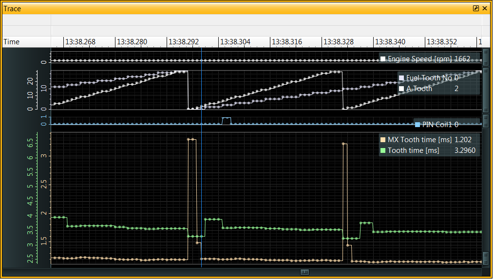
See the long tooth interval detected in MX Tooth Time when A Tooth = 0
The long tooth appears to be in 2 parts of 3.296 and 1.482 ms, with the regular teeth spaced at 1.185 ms.
This is from a 30-2 wheel so the missing tooth interval should be approximately 3x the regular teeth interval.
Notice that the Tooth Time channel has major discontinuities; it is expected that the internal teeth (decoded by the tooth control table) are regularly spaced and so a more constant value is expected here.
Correct Edge
With the Crank Rising Edge and Crank Falling Edge swapped we get just a single long MX Tooth Time 3.754 ms, equal to 3 regular teeth (on a 30-2 wheel) as expected. The regular teeth are spaced at ~1.243 ms:
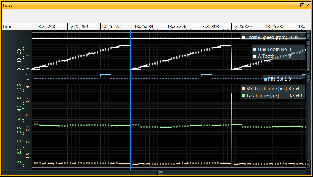
3.754ms / 1.243ms = 3.02 teeth
Also notice that the Tooth Time and A Tooth channels are smoother, meaning that the edges are interrupting the ECU more reliably.
If you are unable to start the engine and idle, it is possible to get the timing wheel running at a steady speed by removing the spark plugs (to avoid compression) and using the starter motor to turn the engine over. This will allow the ECU to log the crankshaft position data without the engine running. For safety, any injection and spark outputs can be disabled in the ECU calibration for this test.
Crankshaft Position Sensor Filtering
Hardware Filtering
- T1 Filter Below - RPM value below which the T1 filter is active.
- T1 Low Sens Above - Reduces the sensitivity of the T1 input above this RPM value, can be useful for VR sensors.
- Crank Filter - Time window, in microseconds, for filtering edges on the crank sensor input.
Software Filtering
- Tooth Short Ignore - Enables software filtering of short tooth intervals. This is useful for filtering out noise on the crank sensor input.
- Tooth Short Running - This is a percentage of the last valid actual tooth interval, edges detected that are less than this percentage are rejected.
- Tooth Short Start - When cranking (starting) the engine, before synchronization is achieved, Stat Sync'd == OFF, software filtering uses a fixed time interval for rejecting edges - edges detected that are less than this interval will be rejected.
When running, Tooth Time x Tooth Short running is used to determine the minimum tooth interval that will be considered a valid tooth event.
The calculated value for the short tooth test is stored in A Tooth Short Test.
If a short tooth is detected, it will record this information in:
- A Tooth Short [ms] - captures captures MX Tooth Time
- A Tooth Short No - captures A Tooth
- A Tooth Short Rev - captures Cam count MX
This information will be recorded regardless of whether Tooth Short Ignore is set.
Cam Sensor
Overview
A cam sensor is used to determine the position of the camshaft, typically relative to the Crank Sensor.
Warning
If the Sync Channel T option is changed during the cam sensor configuration, the ECU must be power-cycled before the change will have an effect. Before power-cycling, ensure that the calibration has been committed to Non-volatile memory (NVM).
Camshaft Position Sensor
If a camshaft position sensor is required, similarly to the crank sensor, it is usually a Hall effect sensor or a VR (Variable Reluctance) sensor. The sensor is typically connected to ECU timer T2 which has a software selectable pull-up resistor. It is possible to use a different timer input if required but T2 is the most common choice.
| Sensor Type |
T2 Pull-up |
| Hall Effect / Optical |
Yes |
| VR / Inductive |
No |
As with the crank sensor the cam synchronization edge should be configured.
If you are planning on using the VVC (Variable Valve Control) features then T2 should be configured for both edges, with the appropriate edge for Cam or 4 stroke cycle synchronization selected by the Sync channel T option. VVC control would require configuration with the other direction edge where appropriate (VVC1 source T, VVC2 source T, VVCX1 source T, or VVCX2 source T).
For example:
| Option |
Value |
| T2 Rising Edge |
ON |
| T2 Falling Edge |
ON |
| Sync channel T |
“T2 Rise” |
If not using T3-T12 timing inputs they can be switched off with T3 - T12 Disable to avoid any additional CPU overhead.
Camshaft Sensor Filtering
Like the crank sensor, the cam sensor can have hardware filtering applied to it:
- T2 Filter Below - RPM value below which the T2 filter is active.
- T2 Low Sens Above - Reduces the sensitivity of the T2 input above this RPM value, can be useful for VR sensors.
Engine Cycle Sync (Camshaft)
Overview
On 4 stroke engines where sequential injection and/or ignition is required, the ECU must synchronize to the correct revolution of the engine cycle so that the correct fuel and spark events are generated.
The crank wheel typically rotates once per revolution and therefore does not provide the ECU with enough information on its own.
However, the camshaft rotates once per cycle (2 revolutions of the crankshaft) and a sync signal from the camshaft can be used to determine the engine cycle.
Camshaft Sync
The ECU counts the occurrence of rising or falling (or both) edges from the cam sensor.
The counter, typically T2R counter (rising) or T2F counter (falling), is captured at an actual crank tooth Sync Test A Tooth and is reset to zero to begin counting again; the counter will be reset every crank revolution at the specified tooth.
Example:

In this example with a 8-1 crank wheel, there are 2 rising edges in the 1st crank revolution and 1 rising edge in the 2nd crank revolution.
The synchronization test point may be adjusted using the Sync Test A Tooth option.
Sync Test A Tooth is the actual crank tooth number (i.e. not an internal tooth number) at which the camshaft counter is captured and reset to zero on every crank revolution. The value is captured into the Cam Tooth Count channel.
Sync Teeth is the number of Cam teeth expected at Sync Test A Tooth when testing for synchronization if the engine is within the expected half of the 4-stroke cycle.
If Sync Test A Tooth were set to 6 in this example (corresponding to the 7th tooth of the crank wheel, counting from 0), then the counter would be set to 2 in the first revolution and 1 in the second revolution.
Setting Sync Teeth to 2 would result in synchronization to be achieved on the 1st crank revolution. If set to 1 then synchronization would be achieved on the 2nd crank revolution.
During the ‘synchronization’ portion of the tooth control table, the captured counter value is tested against the Sync Teeth value.
Warning
It is essential that the cycle detection is unambiguous, otherwise the ECU may randomly synchronize to the wrong cycle.
It is recommended to use data logging and/or an oscilloscope to verify the configuration.
Note
It is not possible to set Sync Test A Tooth to the missing tooth position, as the ECU would not detect an “A Tooth” at that point.
Variable Valve Control Systems
On variable cam control systems, the timing of the camshaft signal varies with respect to the crankshaft signal.
Considering the example diagram again, if the camshaft was in its most retarded position at that point then the ‘Cam’ signal could shift to the left by up to 80 degrees (almost 2 Actual Teeth in this example).

The original example with Sync Test A Tooth set to 6 would still be correct, when counting rising edges, for either cycle 1 or cycle 2 if the cam signal were shifted to the left by as far as 2 teeth.
However, suppose Sync Test A Tooth was set to 4. There would be multiple issues:
- In the first revolution, the ECU would detect either 1 or 2 teeth, depending on whether the camshaft position was advanced by VVC.
- In the second revolution, Sync Test A Tooth closely coincides with the cam signal, and there is a race between the crank signal and cam signal - small timing variations could cause unreliable detection of the cam signal.
In both cases, the cycle detection would be highly unreliable.
Edge Selection
Depending upon the cam sensor configuration, the ECU could be counting rising edges, falling edges or both.
The cam sensor edge direction may be selected by a combination of T2 Rising Edge, T2 Falling Edge and Sync Channel T.
It is possible to use timers other than T2 for cam synchronization, but T2 is the most common.
Engines with Variable Valve Control (VVC / VVT) would typically require both edges to be enabled with Sync Channel T set to either “T2 Rise” or “T2 Fall” so that only the rising or falling edge of the cam signal is used for engine cycle synchronization.
The edge selection may require adjustment to improve engine cycle detection.
If you are using a VR (Variable Reluctance) sensor for the Cam sensor then there may only be 1 valid edge due to the nature of signals from VR sensors - see Crank Sensor.
Sync 2 (Reliably Synchronize Within 1 Revolution)
An optional feature is available to support synchronization within a single crank revolution.
If Sync 2 Active is set to ON, then the cycle shall also be matched using Sync 2 Teeth.
If Cam Tooth Count matches Sync 2 Teeth then synchronization will be achieved (Stat Sync'd will be set to ON) and the value of Sync 2 Fuel Tooth will be placed into Fuel Tooth and the value of Sync 2 Spark Tooth will be placed into Spark Tooth to ‘jump’ these important clocks to the next half of the cycle.
Considering the example again:
For sequential injection + ignition with 4 internal teeth per revolution, this example ECU could be configured with:
| Option |
Value |
| Sync Teeth |
2 |
| Sync Test A Tooth |
6 |
| Sync 2 Active |
ON |
| Sync 2 Teeth |
1 |
| Sync 2 Fuel Tooth |
4 |
| Sync 2 Spark Tooth |
4 |
| Fuel Teeth |
8 |
| Spark Teeth |
8 |
Options / Channels
| Option |
Description |
| Start No Cam Sync |
The ECU will not attempt to synchronize to the camshaft while cranking (starting) the engine. |
| Sync Channel T |
Selects Cam synchronization input timer (e.g T2 Rise) |
| Sync Teeth |
Number of teeth expected to unambiguously identify 1 revolution in the engine cycle. Must be set to 0 if not using a Cam Sync input. |
| Sync Test A Tooth |
The actual crank tooth number at which the camshaft counter is captured and reset to zero. This is the actual crank tooth (A Tooth) number, not the internal tooth number.
Care should be taken, particularly with systems using VVC, to ensure reliable detection across the range from most retarded to most advanced camshaft positions. |
| Cam Tooth Count |
Value of the sync channel (e.g. T2R counter) when A Tooth reaches Sync Test A Tooth |
| Cam Tooth MX |
Value of Cam Tooth Count when ‘MX’ (Missing / Extra tooth) synchronization tested. |
| Sync 2 Active |
Enabled Sync 2 feature. |
| Sync 2 Teeth |
Number of teeth to identify 2nd revolution in the engine cycle. |
| Sync 2 Fuel Tooth |
Value to set in Fuel Tooth if Sync 2 is achieved. Jumps the injection ‘clock’ to the next half of the cycle. Should be set to the number of internal teeth per revolution, if sequential injection is required. |
| Sync 2 Spark Tooth |
Value to set in Spark Tooth if Sync 2 is achieved. Jumps the ignition ‘clock’ to the next half of the cycle. Should be set to the number of internal teeth per revolution, if sequential ignition is required. |
Actual Teeth vs Internal Teeth
Overview
There is a difference between actual teeth on the crankshaft wheel and internal teeth used by the ECU for triggering ignition or injection events.
Internal teeth always coincide with actual teeth but they are arranged such that they are at evenly spaced crank angles.
Actual Teeth vs Internal Teeth
Events from ‘actual teeth’ on the crankshaft wheel cause the ECU’s CPU to be interrupted. The ECU decides whether these events are ‘active edges’ aka ‘internal teeth’ that may be used for triggering ignition or injection events.
If using a missing / extra tooth strategy, the actual tooth events are not evenly spaced. The ECU is able to detect this un-even spacing to identify missing / extra teeth.
If the engine cycle can be determined from a camshaft sensor, and sequential injection or ignition is required, then the Fuel Teeth and Spark Teeth options should wither be set to the same value as the number of internal teeth (e.g. wasted spark) or to double the value (sequential).
Synchronization
Overview
Once the crank / cam sensors are configured, the synchronization strategy and tooth pattern must be set up to be able to synchronize the ECU with the engine.
When cranking / starting the engine, the ECU will initially be in an unsynchronized state. The ECU will not be able to determine the engine cycle position until synchronization is achieved.
When the ECU reaches the synchronized state, the Stat Sync'd channel will be set to ON.
During cranking, the ECU uses a different control strategy to normal running.
Synchronization Strategy
The most common synchronization strategy is to use a Missing tooth (or eXtra tooth) on the crankshaft wheel, GEMS ECUs refer to this as the Sync MX strategy.
There are 4 synchronization strategies available, controlled by 3 options. These options must be set in a mutually exclusive way:
- Sync MX - Missing / extra tooth/teeth on the crankshaft wheel.
- Sync Cam Count - Simplest strategy, uses the camshaft sensor to determine the engine cycle position, prefer Sync Crank S count if possible.
- Sync Crank S Count - Similar to Sync Cam Count, counts the number of crankshaft teeth between camshaft teeth.
- Sync Cam - when the above 3 options are OFF. Ignores the Tooth Control table and used camshaft signal to subdivide the engine cycle.
Subsections of Synchronization
Sync MX
Overview
The Sync MX strategy is the most common synchronization strategy. It uses a missing tooth / teeth (or an extra tooth) on the crankshaft wheel to determine the engine cycle position.
Sync MX Options
The following options are used to detect the missing or extra tooth:
| Option |
Description |
| Sync MX |
ON |
| Sync Cam Count |
OFF |
| Sync Crank S Count |
OFF |
| Sync Crank Divider |
OFF. This option has a major impact on timing interrupts and changing it requires an ECU reset. |
| Missing |
Number of missing or extra teeth. Allowed values 0, 1, 2, -1. A value of -1 indicates the wheel uses an extra tooth (e.g. Honda 12+1). |
| MX Sync Test |
Number of actual teeth before the missing tooth since the last missing section. For wheels with only 1 missing section or 1 extra tooth, set this to the physical number of teeth - 1. So for e.g. 36-2 this should be 34-1, which is 33. For more complex wheels with multiple missing sections (e.g. Rover K), set to the longest run of teeth without any missing teeth between them. |
| MX Time |
Threshold for Missing Tooth detection. Percentage of prior tooth interval time to predict minimum interval to next tooth. |
| Start MX Time |
Threshold for Missing Tooth detection (when cranking). |
| Sync Teeth |
Cam Synchronization, count of Cam sensor events that must occur to reset Fuel Tooth No and Ign Tooth No. |
| Test not Sync'd |
Set to ON so that while cranking, all opportunities are used for synchronization |
| Sync off Above |
Ignore the Cam sync above the specified Engine Speed, if non zero. This may be required at higher RPMs if cam and crank interrupts can interfere with each other, reducing timing precision. |
| Sync Err R/S |
Result in loss of synchronization (Stat Sync'd => OFF) if this number of Sync errors are detected. |
| Sync Test A Tooth and Sync Test A enable |
move cam synchronisation decision at a specific A Tooth, rather than synchronisation test at last valid entry in Tooth control table. This is may be useful with variable cam control systems, where the cam signal used for synchronisation crosses the old fixed decision point. Only used with “Sync MX” Strategy. |
Using a value for ‘Missing’ of 1 may be acceptable for wheels with 2 missing teeth in a row, depending upon the value of MX Time.
The value of MX Time is a balance between the maximum tolerable deceleration of the engine and the ability to detect the missing tooth.
MX Time or Start MX Time is used to make d Tooth Time that is compared with the new tooth time to detect the missing or extra tooth. If detected it is displayed in Miss Time.
This is a scaling factor for the tooth interval for giving a lower bound on when the next tooth should arrive.
If there are missing teeth then either 1 or 2 whole intervals will be added to this value, depending upon the value of Missing. If there is an extra tooth then no extra intervals are added.
When the first tooth after the missing section on the wheel is detected then this deadline should be missed - and the ECU will consider this event as having just passed the missing tooth.

For each time the Tooth Control table is successfully processed, the ECU will decrement the Sync good count channel until it reaches 0.
Sync Cam Count
Overview
Simplest synchronising strategy, where possible use Sync Crank S Count.
Where Cam Count = Sync teeth
Cam count is the number of cam teeth between crank teeth, as in old Subaru pattern and Dodge Viper.
Examples
Toyota
24 even crank teeth per engine cycle with 1 cam tooth.
- Tooth Control table is 0-23 = 5, 24 = 3
- Sync Cam Count = ON
- Sync Crank S Count = OFF
- Sync MX = OFF
- Sync Teeth = 1
- MX Sync Test = 24
Old Subaru
3 crank teeth per cylinder event.
- Tooth Control table is 4,5,6, 4,5,6, 4,5,6, 4,5,6, then at 12 = 3
- Sync Cam Count = ON
- Sync Crank S Count = OFF
- Sync MX = OFF
- Sync Teeth = 1 or 3 there are two 2s
- MX Sync Test = 12
- Ignition range = 0.50 teeth
- Crank Alt Fire = ON
- Start Ignition = -10
Sync Crank S Count
Overview
Where SS Tooth No = MX Sync test and Sync Tooth = Sync teeth
SS Tooth No is the number of internal crank teeth between cam teeth.
Sync tooth is the value of Fuel tooth at the synchronising cam tooth.
Sync Crank S Count Options
| Option |
Description |
| Sync Crank S Count |
ON |
| Sync MX |
OFF |
| Sync Cam Count |
OFF |
| Sync Cam Width |
OFF |
| Sync Crank Divider |
OFF. This option has a major impact on timing interrupts and changing it requires an ECU reset. |
| Missing |
Set to 0 since there are no missing / extra teeth. |
| Sync Teeth |
|
| MX Sync Test |
|
Examples
Honda S2000
24 even crank teeth per engine cycle with 3 cam teeth at TDC for only 3 cylinders.
- Tooth Control table is 0-23 = 5, 24 = 3
- Sync Teeth = don’t care - See channel Sync Tooth or Cam tooth1, the cam tooth for synchronisation relative to crank.
- MX Sync Test = 12 - See channel SS Tooth No, the number of internal teeth between cam teeth at the synchronising cam tooth, the other possibility 6 is not unique as it occurs twice per engine cycle.
Toyota
24 even crank teeth per engine cycle with 1 cam tooth.
- Tooth Control table is 0-23 = 5, 24 = 3
- Sync Teeth = 1
- MX Sync Test = 24
Simple crank trigger
Edge at 45deg 4 teeth cycle, no cam synchronisation.
- Tooth Control table is 0-2 = 1, 3 = 5, 24 = 3
- Sync Teeth = 0
- MX Sync Test = 4
Adjust ignition range for useful +/45 degrees = 0.5
Ford P8 L8
4 even crank teeth per engine cycle with 2 cam teeth.
- Tooth Control table is 0-7 = 5, 8 = 3
- Sync Teeth = don’t care - See channel Sync Tooth or Cam tooth1, the cam tooth for synchronisation relative to crank)
- MX Sync Test = 6 - See channel SS Tooth No, the number of internal teeth between cam teeth at the synchronising cam tooth, the other possibility 2 is not as strong.
- Fuel Teeth = 8
- Spark Teeth = 4 for wasted spark
- Wheel Teeth = 4
Sync Cam
Overview
Old synchronization strategy used with timing wheels with a high number of teeth without any missing/extra teeth. The camshaft sensor is used to identify the engine cycle position.
| Option |
Description |
| Sync MX |
OFF |
| Sync Cam Count |
OFF |
| Sync Crank S Count |
OFF |
| Sync Cam Width |
ON |
| Sync Crank Divider |
ON. This option has a major impact on timing interrupts and changing it requires an ECU reset. |
| Missing |
Set to 0 since there are no missing / extra teeth. |
| Crank Divider |
Divisor for reducing crank teeth to internal teeth. |
| Cam Width Test |
Number of subdivided teeth that must be seen in order to synchronize. |
| Sync Teeth |
Copied to Crank Div Sync Err if synchronization is lost; number of good sync’s required to set Stat Sync'd to ON. |
If the Sync Cam Width option is ON, synchronization is achieved if Cam Width = Cam Width Test when the Cam interrupt occurs.
In some ECUs this may be MX Sync test.
If the Sync Cam Width option is OFF then synchronization would achieved if SS Tooth No = Cam Width Test when the Cam interrupt occurs. However, SS Tooth No is only set when Sync Crank Divider is OFF or during crank interrupt with the Sync Crank S Count strategy enabled. So this mode is no longer of use in recent firmware versions.
In case of loss of sync, Crank Div Sync Err is set to the value of the Sync Teeth and decremented for each successful Cam synchronization. When Crank Div Sync Err reaches 0, the ECU will consider the engine to be synchronized and will set Stat Sync'd to ON.
Pulse Acc count T1 (aka PA Count T1) is captured at start of T2 interrupt, stored in PA count1 temp. This counts T1 events (crank teeth).
Cam Width receives the number of subdivided crank teeth that have occurred since the last Cam sensor event.
Examples
These are historical examples that may contain errors and have not been re-tested on modern hardware.
Historical BMW M3
135 crank teeth on ring gear, one sync pulse at 1/2 engine speed.
- Crank Divider = 9, giving 15 internal teeth per rev. 24deg/internal tooth
- Ign Range = 2.75
- Fuel Teeth = 30
- Spark Teeth = 15 (wasted spark)
- Cam Width Test = 30 (May be MX Sync Test on some ECUs)
- Sync Cam Width = ON (? original example reported as OFF)
- Sync Crank Divider = ON
Nissan
360 crank teeth (high speed), 4 cylinder slots of different widths, equivalent to 2,3,5,or 5 crank teeth.
- Crank Divider = 15, giving 12 internal teeth per rev. 30deg/internal tooth
- Ign Range = 3.0
- Fuel Teeth = 24
- Spark Teeth = 12 (wasted spark)
- Cam Width Test = 251 (? - needs confirmation)
- Sync Cam Width = ON
- Sync Crank Divider = ON
Use only fast falling edges for crank (T1) and cam (T2).
Tooth Control Table
Overview
The main goal of the Tooth Control table is to subdivide the physical timing wheel teeth (actual teeth) into regularly spaced internal teeth.
RPM Pickup Wizard
The RPM Pickup wizard can be used to calculate the Tooth Control table values, given some common timing wheel types.
Tooth Control Table
The Tooth Control table is a low-level ECU feature that is not obvious but essential to understand if needing to accommodate unusual tooth patterns.
Each site in the Tooth Control table corresponds to the sequence of ECU interrupts (events) from actual teeth passing the crank sensor and are therefore not necessarily evenly spaced in time or angle; there will not be any events in the missing section of the wheel or there may be an extra tooth. Some timing wheels have more than one missing teeth section.
The aim is to select from these events an evenly spaced real-world pattern of internal teeth that can be used to schedule fuelling and ignition events. The internal teeth are used to subdivide the engine cycle into equal parts, and the ECU will increment internal tooth counters for each internal tooth detected, with separate counters for fuelling and ignition.
If using a wheel with 2 missing teeth in a row, for example, then the actual teeth will need to be divided by at least 3 (possibly more) to ensure that no internal teeth fall within the missing section and are also evenly spaced in terms of crank angles. Each internal tooth must coincide with an actual tooth passing the sensor; i.e. an interrupt/event occurs in the ECU for each internal tooth.
It is common to subdivide the timing wheel into 12 internal teeth. For example, with a 36-2 wheel that has 2 missing teeth in a row this can be divided by 3 into 12 equally spaced internal teeth that all coincide with actual teeth.
When actual teeth are detected, the ECU will increment A Tooth and use the value to look up the corresponding site in the Tooth Control table.
Each value in the table is composed of 3 digital ‘bits’ (1/0):
| Value |
Bits |
Function |
| 0 |
000 |
Do nothing. |
| 1 |
001 |
Active Edge (Internal Tooth). |
| 2 |
010 |
Alternate Edge (Used for Crank Alt Fire mode). |
| 3 |
011 |
Reset A Tooth, if loss of sync. Indicates the end of the table. |
| 4 |
100 |
Test for synchronization. |
| 5 |
101 |
Active Edge (Internal Tooth) + test for synchronization. |
| 6 |
101 |
Alternate Edge + test for synchronization. |
| 7 |
111 |
Reserved (do not use this value). |
Unless all sites in the table are required, the value ‘3’ should be placed at the end of the table so that loss of synchronization can be detected; if A Tooth overruns the valid section of the table then the ‘3’ shall be encountered and the ECU will reset A Tooth to 0. The channels Sync Error and Timing Error will be incremented if this event occurs.
It is expected that the synchronization event(s) will be detected before the ‘3’ value is encountered, which would also result in A Tooth being reset to 0.
Active edges (internal teeth) are used to schedule fuelling and ignition events and are indicated by either ‘1’ or ‘5’ in the table. The ECU increments internal tooth counters Fuel Tooth No and Ign Tooth No when an active edge (internal tooth) is encountered in the Tooth Control table.
The Synchronization Test bit (100), when set, will cause the ECU to test for synchronization. This allows for some reduction of CPU load when running at higher RPMs by skipping synchronization checks on all tooth interrupts (events) (which would be occurring much more frequently). This bit is normally set in the tooth control values near the end of the table where the missing / extra tooth is approaching, though for some other patterns there could be multiple synchronization points.
When not synchronized (Stat Sync'd == OFF), the ECU can be configured to test for synchronization on all actual teeth by setting Test Not Sync'd to ON (recommended).
Tachometer Output
Overview
The ECU may be configured to output a tachometer signal to drive an external tachometer. The signal is a square wave with a frequency proportional to the engine speed.
Tacho Edge Table
Tachometer state change events are inserted into the Tacho Edge table. They should be evenly spaced and typically there should be 4 state changes per revolution (i.e. 2 pulses per rev), depending upon the tachometer input requirements.
It is generally best, therefore, to place the state changes at the same A Tooth numbers as equidistant ‘active edges’ in the tooth control table, assuming that it is possible to do so.
The Tacho Pin option specifies which ECU pin the tachometer signal is output from. Check the ECU pinout to determine which pin number this should be set to.
Note
Changing the Tacho Pin option requires an ECU reset to take effect.
If using the RPM Pickup wizard, the Tachometer output can be calculated for you given a pulse-per-rev value. The RPM Pickup wizard assumes that Wheel Teeth is equal to the number of internal teeth.