Using GWv4
Overview
This section is intended as a User Guide for GWv4. Head to the FAQ section for quick answers to common problems or select a topic below for a deeper dive into the subject.
This section is intended as a User Guide for GWv4. Head to the FAQ section for quick answers to common problems or select a topic below for a deeper dive into the subject.
The current unit does not have any other related units that it can convert to. Check that the base unit has been quantified. For more information see Unit configuration.
Yes, please see PC based auto mappingfor more information.
Auto mapping is a useful feature that can adjust base map values in real time to match a target map as closely as possible. This feature can only be used when online and can be enabled in the Log Map Controller . Here, controls for the auto mapping algorithm can be set as described in Log Map Controller.
Let’s go through an example auto mapping procedure on a Lambda Log Map. Before starting, we must make sure that the calibration:
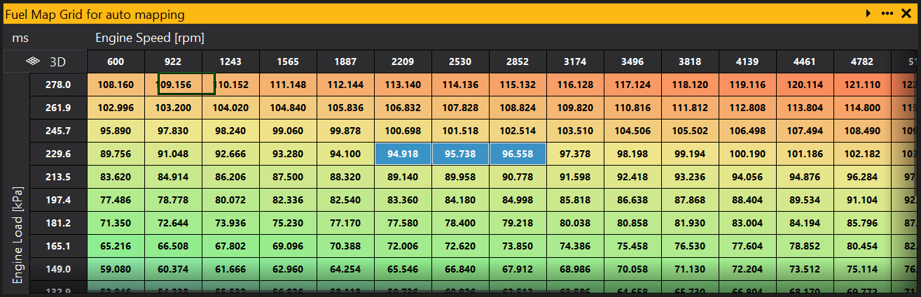
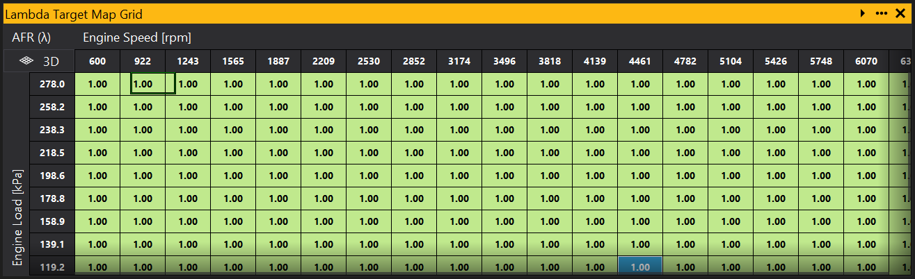
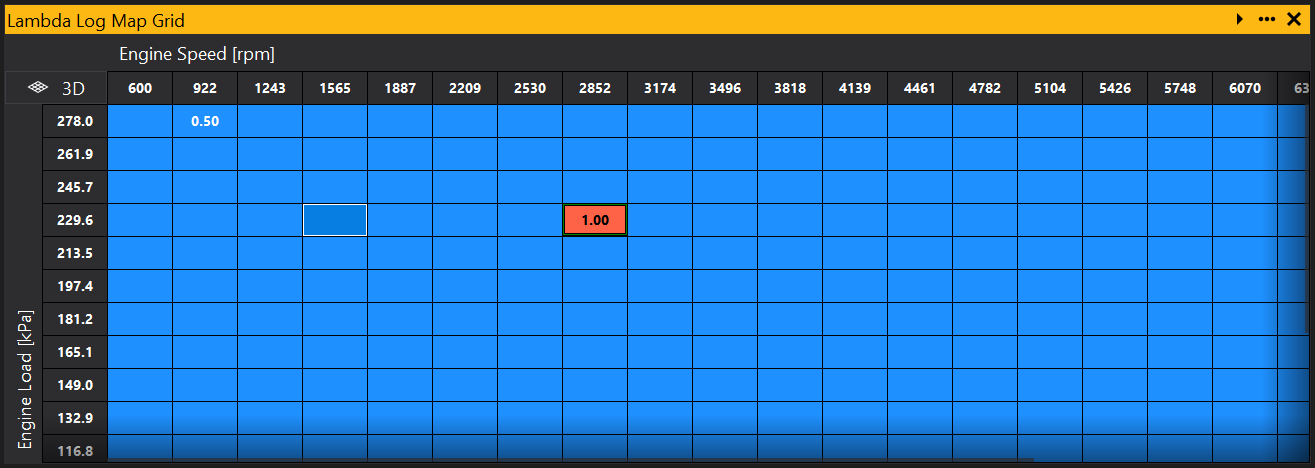
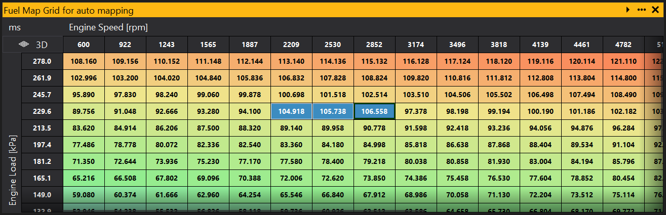
To achieve this we will use the base map of engine load vs engine speed and create a simple target map of lambda set to 1 over the whole map for a simple example (in reality we’d want a richer mixture at lower engine loads and speeds, and leaner at higher). It is better to be conservative and start with a richer target map to avoid overheating the engine. Some GEMS ECUs support closed loop Lambda feedback which have built-in auto mapping. So switch this off if applicable so that GWv4 is the only system changing values through the auto mapping algorithm.
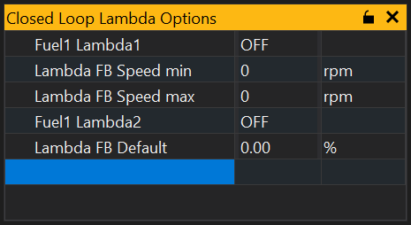
Switch all of the Fuel Lambda options to OFF. Alternatively, set the options Lambda FB Speed Min and Lambda FB Speed Max to 0.
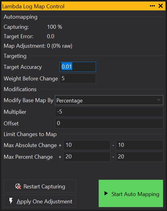
Now we need to adjust the auto mapping parameters in the Log Map controller. The typical accuracy of a wideband oxygen sensor is around 0.01 at Lambda 1 so we’ll set this as the Target Accuracy parameter in the Targeting panel. This value is optimistic as there are several other sources of uncertainty. Once you have enough data to make a good uncertainty estimate, update the target accuracy to this value for more confidence in the results. To average out the noise of the Lambda reading, we’ll set the Weight Before Change value to 5, so that the cell will only be changed after 5 milliseconds at this location.
In the Modifications panel, we’ll select a percentage change to modify the base map by. If using this mode, you can only perform auto mapping on non-zero base map cells. Generally we want the Multiplier to be negative to increase stability. Start with a low value and increase later if the steps in the changes are not large enough. We don’t need to add an Offset so leave as zero.
We’ll set sensible maximum changes of 20% in the Maximum Changes panel. Remember that these are changes from the original cell value.
Lastly, start auto mapping by clicking the button.
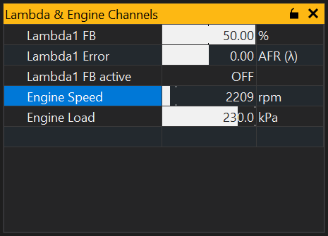
After setting up the Log Map Controller, we can add a Log Map Grid via or a Log Map Graph via . The grid/graph will be empty until auto mapping starts.To start, select a cell and click the Start Auto Mapping button on the Log Map Controller. You can now run the engine on a plan to target the desired cells you wish to auto map. It can also be useful to add the Lambda Error (or Ox Error depending on your ECU) channel to a Channel List to see how the auto mapping procedure is progressing. This channel should tend towards zero as the cell’s target value is approached.
Once mapping is complete, don’t forget to switch back on the other processes that adjust the base map.
Auto mapping may not work for the following reasons:
When configuring units, there may be times where you are unable to select other existing scaled units. This is because there are no available conversions, so you need to select a different base unit.
An example of this issue is the Air-to-fuel Ratio (AFR/Lambda). For some ECUs, Lambda readings are specified in the unitless quantity ‘AFR’. This has no real meaning or relationship to other AFR units, so the base unit needs to be changed to one that is quantified and convertible. To resolve this, select the base unit that matches the current fuel type.
Some of GEMS ECUs provide a user Enumeration/Option List ‘AFR Base Units’ that allows the base units to be recorded in the ECU calibration memory. If this is unavailable, you can create your own using dynamic chained units in user scalars.
Firstly, create your required User Scalars:
[USERSCALAR,AFR Custom,AFR,...] // for exotic fuels
[USERSCALAR,AFR Methanol,afr:AFR Gasoline,...]
[USERSCALAR,AFR Gasoline,afr:AFR Methanol,...]
[USERSCALAR,AFR Diesel,afr:AFR Diesel,...]
// etc
Then create an Enumeration/Option List with these User Scalars:
[ENUM=AfrUnitList,0,AFR Custom,1,AFR Methanol,2,AFR Gasoline,3,AFR Diesel, ...etc]
Then create the Option for the Enumeration:
[AFR Units,,ol(AfrUnitList),...]
Finally, create a new definition for AFR Units using the Option:
[USERSCALAR,AFR Units,O[AFR Units],...]
You will now be able to select the appropriate User Scalar from the AFR Units Option.
Otherwise, the base unit choice must be stored externally to the ECU and GWv4 will not remember your choice. There are a few ways to accomplish this:
Reload the same calibration file every time you connect the ECU.
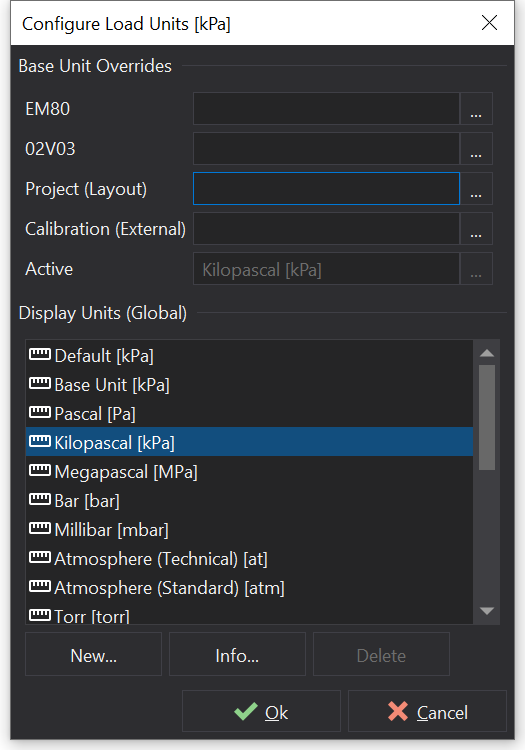
Override the base unit to a particular choice for any or all of the following: ECU types, versions, current project, calibration files on your PC. However, this may only be desirable if you are only ever working with a single fuel type.
Select , scroll down to the desired unit name and click ‘…’ on the right hand side next to the current unit.
Save units whilst in the Configure Units / Scaling window and reload then when needed.
Change the default AFR units to be afr:LA and calibrate the reading to read 1.0 at the stoichiometric ratio. You can then select AFR for different fuel types from that. However, any other calibrations would also need recalibrating because their AFR offset and AFR scalar will be wrong.