Model Integration
This page explains how a CDX application connects to the dash: its project structure, the Model IPC interface, Simulink integration and calibration. Build and run the Quickstart first.
Project Structure
A CD6 application owns its source code and build configuration. The CD6
runtime release is extracted into a cdx-runtime folder inside the project:
 1my-model/
 2  cdx-runtime/        Prebuilt runtime, headers and build tools
 3  main/               Application callbacks and headers
 4  ipc/                DBC definitions for the Model IPC connection
 5  model-generated/    C sources from Embedded Coder, if used
 6  ginmake-generated/  IPC sources generated by Ginmake
 7  build/              Compiled firmware and model package
 8  CMakeLists.txt      Application build configuration
 9  CMakePresets.json   Release and Debug presets
10  cdx-project.json    CDX CLI project configuration
11  model-ipc.json5.in  Ginmake configuration
Keep your changes outside cdx-runtime. The whole runtime folder can then be
replaced to change versions without replacing your application. See
Updating the Runtime.
Model IPC Messages
The model communicates with the dash through the virtual Model IPC CAN channel, not directly through an external CAN connector. Two DBC files define the messages and signals in each direction. Directions are named from the dash perspective:
| Dash direction | Model direction | Ginmake input | CDX_RT_configure_model |
|---|---|---|---|
| Dash transmits on Model IPC | Model receives dash values | rx DBC |
TX_DBC |
| Dash receives on Model IPC | Model sends dash values | tx DBC |
RX_DBC |
flowchart LR
    channels["External CAN / dash channels"] <--> dash["CM7 dash firmware"]
    dash -->|"Dash transmits on Model IPC"| ipc["Virtual Model IPC CAN bus"]
    ipc -->|"Model receives (Ginmake rx DBC)"| model["CM4 model (CDX runtime)"]
    model -->|"Model sends (Ginmake tx DBC)"| ipc
    ipc -->|"Dash receives on Model IPC"| dash
    xcp["XCP on external CAN1/CAN2"] <--> dash
CM7 handles XCP on external CAN1/CAN2, separately from Model IPC.
- Write the DBC files yourself, as in the template’s
ipcfolder, or design the Model IPC messages in Dash Design and export them as DBC files. - Use
port: "ipc"in the Ginmake configuration. Ginmake generates get/set functions and Simulink signals, so the model works with named signals rather than frames. - The build packages the DBC files with the firmware in the
.cdxmodelfile. When you load the package, Dash Design creates a channel for each signal the model sends. It connects each signal the model receives to the existing numeric channel with the same name. Matching ignores letter case and treats spaces and punctuation as underscores. - Keep the application and setup DBCs identical. The firmware records a hash of its DBC interface, and Dash Design rejects packages whose firmware and DBC files do not match. If you change the interface, regenerate the sources, rebuild and reload the package.
Packaging --rx and --tx arguments also use the dash directions. The
example builds already handle this reversal.
Simulink Workflow
For Simulink models:
- Follow the Ginmake Simulink workflow to generate workspace definitions and model integration code.
- Follow the Simulink Projects guide
for the project’s
initialize.m, CDX signals and Dash Design CDX Project Tools builds. - Put Embedded Coder output in
model-generated. The CDX CLI stages it for you. - Call your model’s initialization and base-rate step, either with
CDX_RT_configure_simulinkor frommain/generated.c. See Implementing The Callbacks.
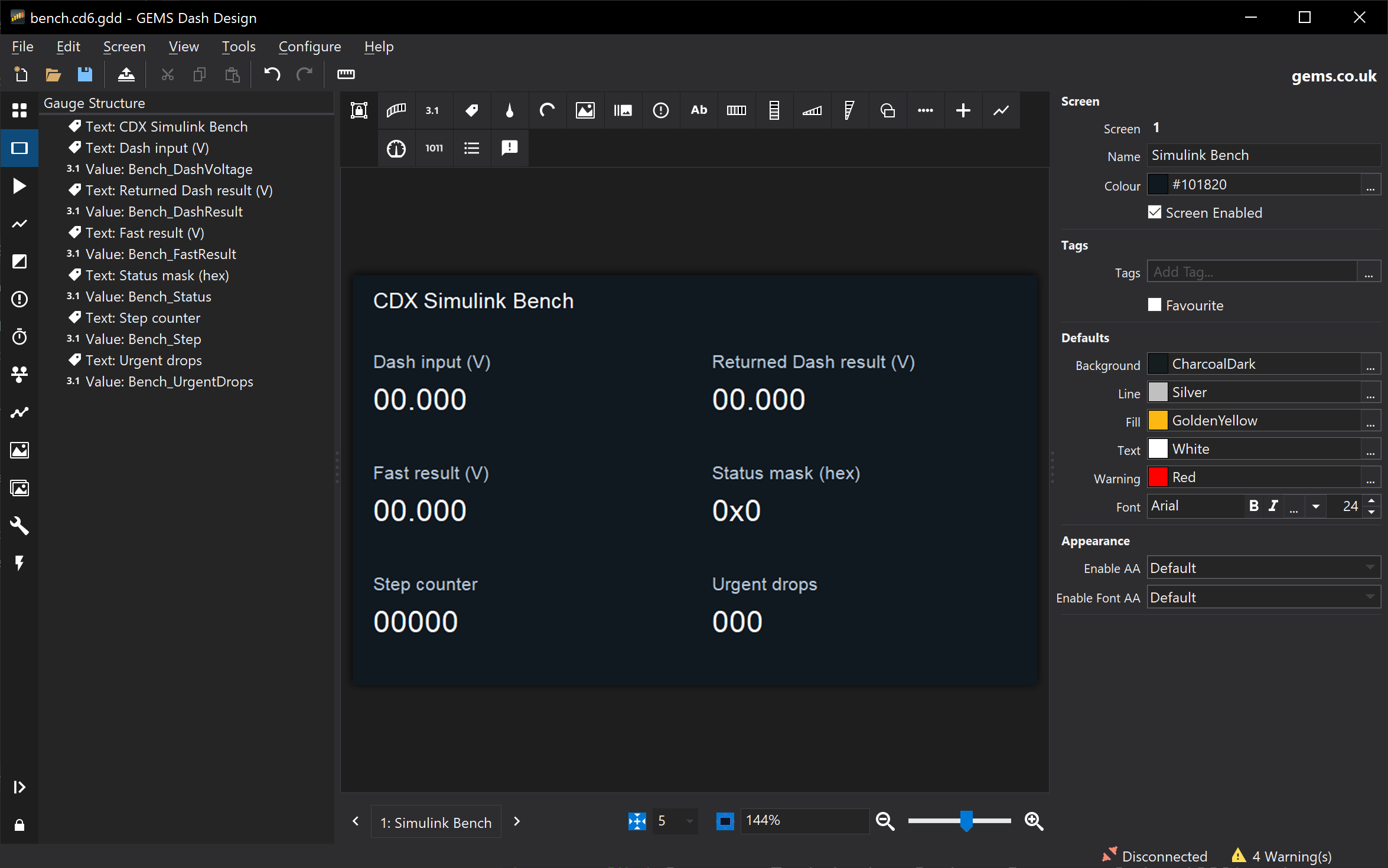
The application template is an IPC adapter, not a complete Simulink project. The Simulink Bench example is a complete model, adapter and Dash Design setup. It steps a stock-block model every 1 ms. Each step conditions Analogue 1 received both through Dash channel evaluation and through the fast ADC API. The example also covers urgent CAN transmit and XCP calibration with nonvolatile storage:
Loading The Model Into A Setup
The build writes the *.cdxmodel package and finalized MDL_FIRM.bin into
build/cm4-release/. Do not deploy MDL_FIRM.raw.bin.
- Load the
*.cdxmodelinto an editable CD6 setup in a compatible GEMS Dash Design release. See Adding a Custom Model to a Setup. - Use the model’s output channels in the setup like any other channel.
- Upload the setup with its embedded model firmware to a CD6 whose firmware
supports the model runtime. Alternatively, use
cdx embedandcdx deploy. See Run It on a CD6. - Check that the model is running by changing an input and watching an output. Uploading alone does not prove that the model has started.
The examples have automated ARM build/package checks. You still need to verify operation on a physical device with your editor, dash firmware and hardware.
Application Notes
Your application provides the five CDX_app_* callbacks, either generated by
CDX_RT_configure_simulink or written by hand. See
Model Callbacks for when
each runs and the rules they must follow.
The image and private RAM limits are each 128 KiB. The default stack is 4 KiB. Inspect your link map and measure execution time and stack use on the board.
Calibration And NVM
The echo example’s optional calibration build supplies a matching A2L. Keep that A2L with its firmware.
- Use restored parameters. Do not reset them to defaults during initialization.
- Request XCP
STORE_CALto persist edits. Persistence requires working dash storage. - Use external CAN1 or CAN2 for XCP, not Model IPC.
The Simulink Bench example shows calibration with nonvolatile storage in a Simulink model.