Simulator Tab
Overview
The Simulator Tab is used to test the setup being edited on a simulated dash.

Running the Simulator
Info
The simulator can only run if there is suitable simulator firmware for running the current setup.
A simulator firmware version may be selected from the drop-down box below the  Play Icon.
If there are no options in the firmware list, it will display “No Firmware” and it will not be possible to start the simulator.
Clicking the Play Icon will start the simulated display using the current setup.
If the setup is changed while the simulator is running, a Setup Changed notification is shown because the simulation may no longer match the current setup. Use the notification’s Restart Simulator button to restart the simulator with the changed setup, or Stop Simulator to stop it.
Display simulators are built from the same code as used by the real display. There may be some differences in behaviour due to differences in the running platform (i.e. the desktop operating system as opposed to an embedded environment).
Firmware Compatibility
When the simulator starts, the setup is checked against the features supported by the selected simulator firmware. If some setup features may not be supported, a Simulator firmware warnings notification is shown; click View Report to see the details.
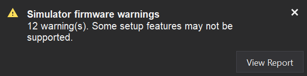
Use the notification’s close button to dismiss it without stopping the simulator. Dismissing the notification does not resolve the warnings.
The report for the last simulator run is also available from Simulator Firmware Report… on the Simulator Tab’s context menu (right-click). Restart the simulator after making changes to the setup.
Simulator Options
Click the Options… button (or select Simulator Options… from the context menu) to configure local launch settings. These settings apply to the next simulator run and are not saved in the display setup. Stop the simulator to change them.
| Option | Description |
|---|---|
| CAN Ports… | Opens CAN Ports & Activity to connect physical CAN interfaces to the simulator, play back ASC files or monitor CAN traffic. |
| CDX Model DLL | For displays with a CDX Model processor, the native model DLL used to simulate the model. If left blank, the CDX_MODEL_DLL environment variable is used. |
| Model Image (optional) | For displays with a CDX Model processor, the model image (.bin) to load. If left blank, the CDX_MODEL_IMAGE environment variable is used. A model image embedded in the setup takes precedence. |
| Startup delay (ms) | Delays firmware start-up by the given number of milliseconds, for example to attach a debugger. Use 0 for no delay. |
Beacon Input
Clicking the  Beacon Icon will simulate a beacon input event, which can be useful for testing lap timing. For GPS lap timing, hold the beacon input for half a second to set the lap start position.
Buttons
For displays with buttons, a button strip beneath the simulated screen allows buttons that may not be represented on the simulated display shell to be pressed. Buttons are labelled with their names (e.g. PL and PR for the left and right paddles); hover over a button to show its full name.
Channels
Values in the Channels list may be modified to simulate their value changing in the display. For CAN channels, this will simulate the sending of CAN frames to the display firmware.
Show Predefined Channels
Includes predefined channels in the channels list. When unchecked, predefined channels are hidden.
Show Used Channels Only
Shows channels that are used by the current screen only.
Show Watched (Checked) Channels Only
Shows only the channels that have been checked (watched) in the channels list.
Waveform
The waveform column indicates if there is a generator defined for the channel. If there is, then the waveform may be enabled/disabled using the checkbox. The waveform will then be generated and sent to the display.
To define a waveform for a simulator channel, select one or more channels, click the Properties… button, and edit the waveform properties.
Connect to GDA
GDA must be running before checking the “Connect to GDA” checkbox.
A data log file may be loaded in GDA and then played back, with channel values being sent to the simulator.
The channel list should update in response.
The data log must have channels that exactly match the names of channels in the display setup.
Other Applications
Other applications could integrate with the simulator to send their own values to it.
The application must implement a named pipe server, with the pipe name “GemsDAChannelDataServer”.
Data is sent over the pipe using JSON documents, separated by NULL characters, of the form:
{
    "cd":[
        { "n": "Channel1", "v": 0.2 },
        { "n": "Channel2", "v": 3.14159 }
    ]
}