LEDs
Overview
LED setup varies between display types. Some displays only support rule-based configuration: LEDs (Rule Based) .
Other displays support a simpler channel-per-LED configuration.
Options
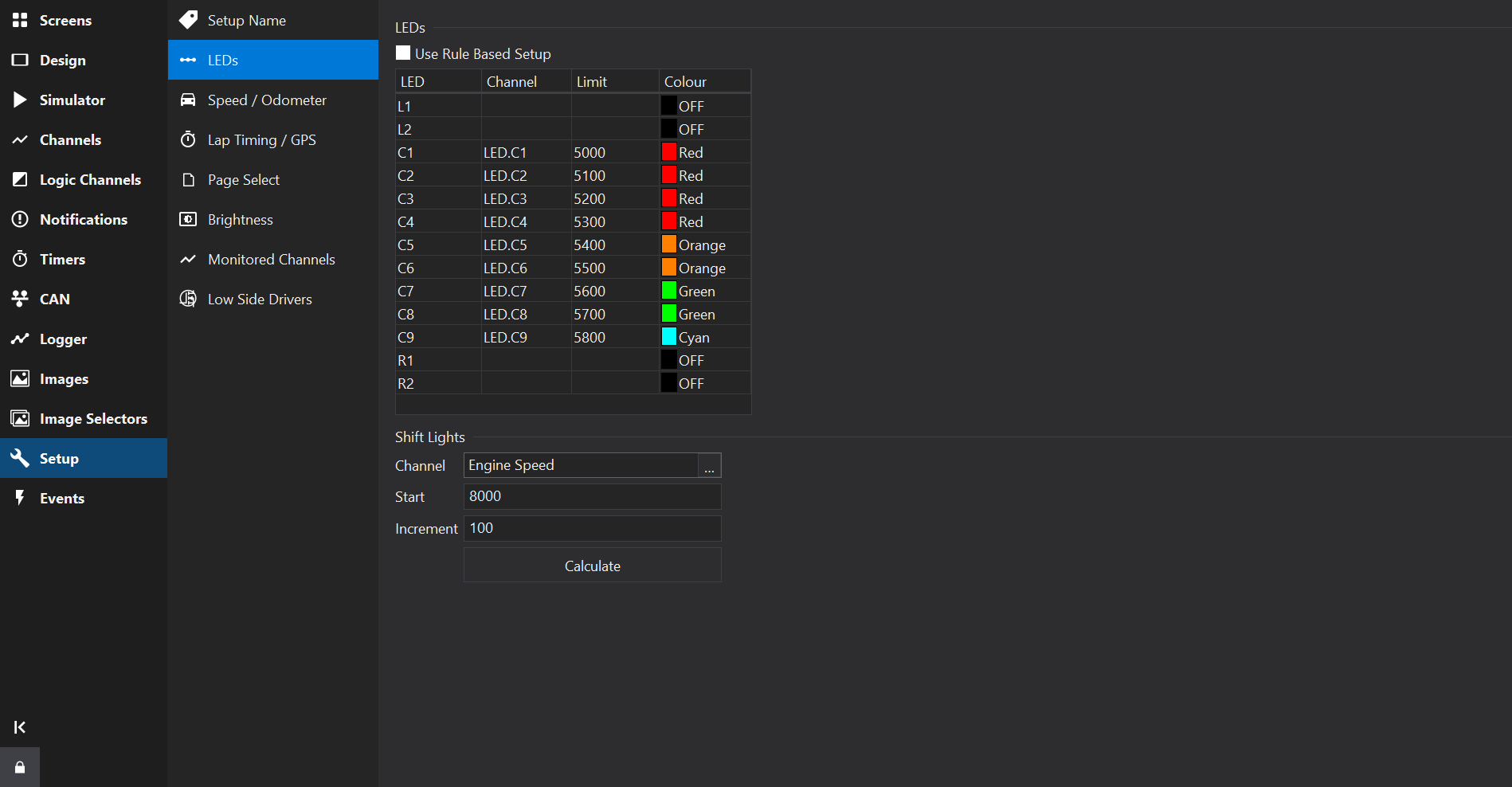
Use Rule Based Setup
If available for the current display type, checking the Use Rule Based Setup allows complex LED patterns and rules to be specified.
See LEDs (Rule Based) for more details.
LED List
The LED List displays a fixed list of the LEDs available on the display.
Channels may be used to drive the LED, optionally with a limit and a colour.
For some displays, a flash channel may also be specified per LED (on/off). If activated, the LED will flash at the rate configured for the gauge as a whole.
Colour Channel
Channels may be used to select the colour of an LED. The colour selected by the channel value depends on the display type, but for current displays the following table is used:
| Value | Colour |
|---|---|
| 0 | Off |
| 1 | Red |
| 2 | Green |
| 3 | Blue |
| 4 | Orange |
| 5 | Magenta |
| 6 | Yellow |
| 7 | Cyan |
| 8 | White |
| 9 | Channel (Direct Drive) |
| 10 | Channel RGB111 (Direct Drive) |
The RGB111 colour space is a 3-bit colour space with 1 bit per colour channel (Red, Green, Blue), meaning that input channels have a different colour mapping and should be in the range 0-7.
Shift Lights
Depending upon the display type, a shift light pattern may be generated.
To generate a typical shift light pattern, set a Channel, a Start value and an Increment value and then click the Calculate button to generate the pattern.