The Channels Tab provides configuration of channels in the display.
The Channels Tab lists a subset of all channels.
Channels typically convert values coming from sources into scaled values and can be routed to other channels, gauges, and in some cases externally (e.g. using CAN Transmit).
Select a channel from the list on the left hand side to view / edit the channel configuration.
Common Fields
Channel Name
The channel may be renamed in the Channel Name field. If a channel is renamed, any references to it (e.g. from Gauges) shall be updated. Channel names must be unique; if the rename would result in a duplicate name then an error will be posted and the Channel Name field will revert to the original name.
Predefined channels can’t be renamed.
Primary Input
Most channels have a single input. This may be a ‘Source’ or another channel.
CAN channels are created using the CAN Receive
tab. These have an implicitly created ‘Source’ that can’t be changed.
Filter
An ‘in-place’ filter chain may be specified on most channel types. Filter chains insert hidden channels in the setup that modify the channel value in various ways, such as averaging (box filtering) or presenting error text when the input has timed out.
Alternatively, a filter channel may be created to provide an alternative filtered version of the channel with a different name.
If not set, the input units will be implicitly set to the output units of the Primary Input channel.
Otherwise, the Input Units specify the expected units of physical values coming into this channel. If the primary input produces values with a different physical unit then values will be pre-converted to the expected input units, if possible.
To the right of the Input Units selector is a copy button to clone the input units from the Primary Input.
Output Units
Indicates the physical units of values following any scaling specified by the channel configuration. For example the channel may be a Function (Lookup Table) Channel
that has input units of Volts and converts this to a temperature in Celsius. The input and output units make this conversion clear.
Display Units
These are the physical units that the channel should be displayed in. The channel configuration may produce a specific set of units but the user preferentially would prefer another unit. For example, a Function (Lookup Table) Channel
may output celsius but it is preferred to display temperatures in Fahrenheit.
Next to the Display Units selector is a dropdown box to select the Display Units policy. By default, this will be set to ‘Match Preferences’:
Match Preferences
Automatically set the display units for this channel when the global unit preferences are changed. For example, if the Output Units are a temperature unit and the unit preferences selects ‘Fahrenheit’ for temperature units then the display units shall automatically be changed to ‘Fahrenheit’ and the physical value of the channel shall be rescaled from the selected Output Units.
If there is not a global unit preference for the Output Units type then this is equivalent to the ‘Match Output’ policy.
When ‘Match Preferences’ is selected a Unit Preferences button is show to the right of the drop-down box to open the Unit Preferences. The preferences are also available from the menu action Configure | Unit Preferences..., see Unit Preferences
for more details.
Warning
Match Preferences will not automatically track Unit Preferences if ‘Auto Apply to Channels’ is not checked in the Unit Preferences dialog.
Legacy display setups will default this setting to ‘Off’ to avoid a change in behaviour when coming from a legacy version of the software.
Match Output
Track the selected Output Units for the display units - if the Output Units are changed then the Display Units shall be automatically updated to match.
Override
Always convert the output units to the selected Display Unit, if a conversion exists.
Adding / Removing Channels
Towards the bottom right of the Channels List, use the button to add a new channel, and the button to remove the selected channel(s).
Removing CAN channels from this list shall also remove the channel from the signals table on the CAN Receive
Tab.
Predefined Channels
Depending upon the display type, there will be some pre-defined channels in the setup. New setups will have these channels added automatically.
When loading existing setups, if any predefined channels are missing, they shall be automatically added when the setup is loaded.
Check the “Show Predefined” checkbox to the lower left of the Channels List to include predefined channels in the Channels list. Predefined channels are shown in a different colour and usually can’t be edited or removed from the setup.
CAN Channels
Using the context menu (right click) on the channel list provides an option to show the channel in the CAN Receive
.
There are a number of channels that are automatically added to the display setup. These cannot be deleted as they can be critical to the display operation.
By default, the pre-defined outputs are hidden from view in the Channels Tab
and are only visible as appropriate inputs when configuring other channels or gauges. They can be made visible in the Channels Tab
by checking the Show Predefined Outputs box.
Subsections of Predefined Channels
Analogue Channels
Overview
Most Display Module types have multiple analogue inputs named A1 Raw, A2 Raw etc.
Analogue inputs typically have 12 bit resolution with a range of 0 to 4095.
CAN Status Channels
Overview
CAN status channels such as CAN 1 Status channel can be used to display the state of the current CAN port by setting it as the input to a Text Input Gauge
gauge.
More than one status channel may be available if the Display Module supports multiple CAN ports.
CAN Status Messages
Status
Description
CAN 1 OK
The CAN bus is working correctly.
CAN 1 DISABLED
The CAN bus has not been setup or is not present.
CAN 1 BUS OFF
A serious error has occurred on the CAN bus - this may be due to the wrong baud rate being set or the CAN wires shorted together.
CAN 1 Disconnected
No messages have been received by the display in the last three seconds.
CAN 1 Warning
Errors are present on the bus; this may be due to incorrect baud rate or noise.
CAN 1 Tx not acknowledged
A message sent by the Display Module has not been acknowledged by any nodes on the network.
CAN 1 TOO MANY MESSAGES
The total number of messages that the display is being asked to receive and transmit exceeds the capability of the CAN hardware. This can be overcome by using CAN message masks.
CAN 1 Rx Timeout
Traffic is present on the bus but none of the channels that the Display Module has been set up to monitor on the current screen (and monitor screen) are present.
Lap Timing Channels
Overview
The Display Module can perform lap timing when connected to a suitable beacon. To configure lap timing see Lap Timing / GPS
.
Data Types
Most lap timing channels are ’time’ types; Gauges should use time based formatting to display them (see Value Formatting
).
If lap timing channels are used as inputs to other channels, they are first converted to milliseconds and sent as a floating point number instead of as a time value.
Tip
To display lap time deltas on Bar Gauges
, create a Linear (Scalar) Channel
with the pre-defined delta channel as an input. This will convert the time to a floating point number, making it possible to use it in a bar type gauge.
Lap Timing Channels
Channel Name
Description
Current Lap Num
The current lap number. This is zero until the first beacon has been passed then increments by 1 each time a beacon is passed.
Current Lap Time
The elapsed time of the current lap. When a beacon is passed, the lap time will freeze for 3 seconds to show the time of the lap just completed before resuming to show the new current lap time.
Last Lap Num
The number of the last lap just completed.
Last Lap Time
The lap time of the lap just completed.
Fastest Lap Num
The number of the fastest lap in the current session.
Fastest Lap Time
The time of the fastest lap.
Fastest Lap Delta
The time difference between the last completed lap and the previous fastest lap.
Last Lap Delta
The time difference between the last completed lap and the previously completed lap.
Fastest Lap Average Speed
The average speed of the fastest lap.
Last Lap Average Speed
The average speed of the last lap.
Predicted Lap Time
The predicted lap time of the current lap based on the fastest lap.
Predicted Fastest Delta
The predicted difference between the current lap and the fastest lap.
Predicted Last Delta
The predicted difference between the current lap and the last lap.
Screen Selector
Overview
The Screen Selector channel is derived from an analogue input (depending on the type of module).
It uses a lookup table that is pre-calibrated for a 12 position switch using 1k resistors.
If you have used a different page select switch, the lookup table may need to be recalibrated.
CAN Page Select
If page select is being done via CAN or a button press, the page select input can be used as an analogue input (shown as A00 Raw).
To prevent the input also changing pages, edit the Screen Selector lookup table; set the first row to have an input of 0 and an output of 0 and the seconds row to have an input of 4096 and an output of 0.
Speed Channels
Overview
Most Display Module types have multiple speed inputs and these are shown in the setup as channels called Speed 1 Raw, Speed 2 Raw etc.
The raw speed outputs are scaled in Hz.
Bitmask Channel
Overview
Bitmask Channels are used to mask off bits from a raw (32 bit) input.
This is useful when data is received from the ECU that contains information for two different outputs.
For example, the lower 4 bits of a value may be used to determine gear position while the upper 4 bits determine diff mode.
Options
Mask (hex)
The mask, in hexadecimal format.
Any bits in the input value that are also set in the mask are allowed through, otherwise the bits shall be set to zero.
If used as a derived output, internal values in the display are represented as double precision floating point numbers. Floating point numbers are converted to integer prior to masking.
Hexadecimal format is used here since it lines up nicely with bits. A single hexadecimal character represents 4 bits:
Hex
Binary
0
0000
1
0001
2
0010
3
0011
4
0100
5
0101
6
0110
7
0111
8
1000
9
1001
A
1010
B
1011
C
1100
D
1101
E
1110
F
1111
Supported By Displays
Display
Supported?
CD34
Yes
LDS4
Yes
CD32
Yes
LDS35
Yes
LDS35_L
Yes
CD6-43
Yes
GLW-43
Yes
LFRW-43
Yes
ZDU-L
Yes
ZDU-P
Yes
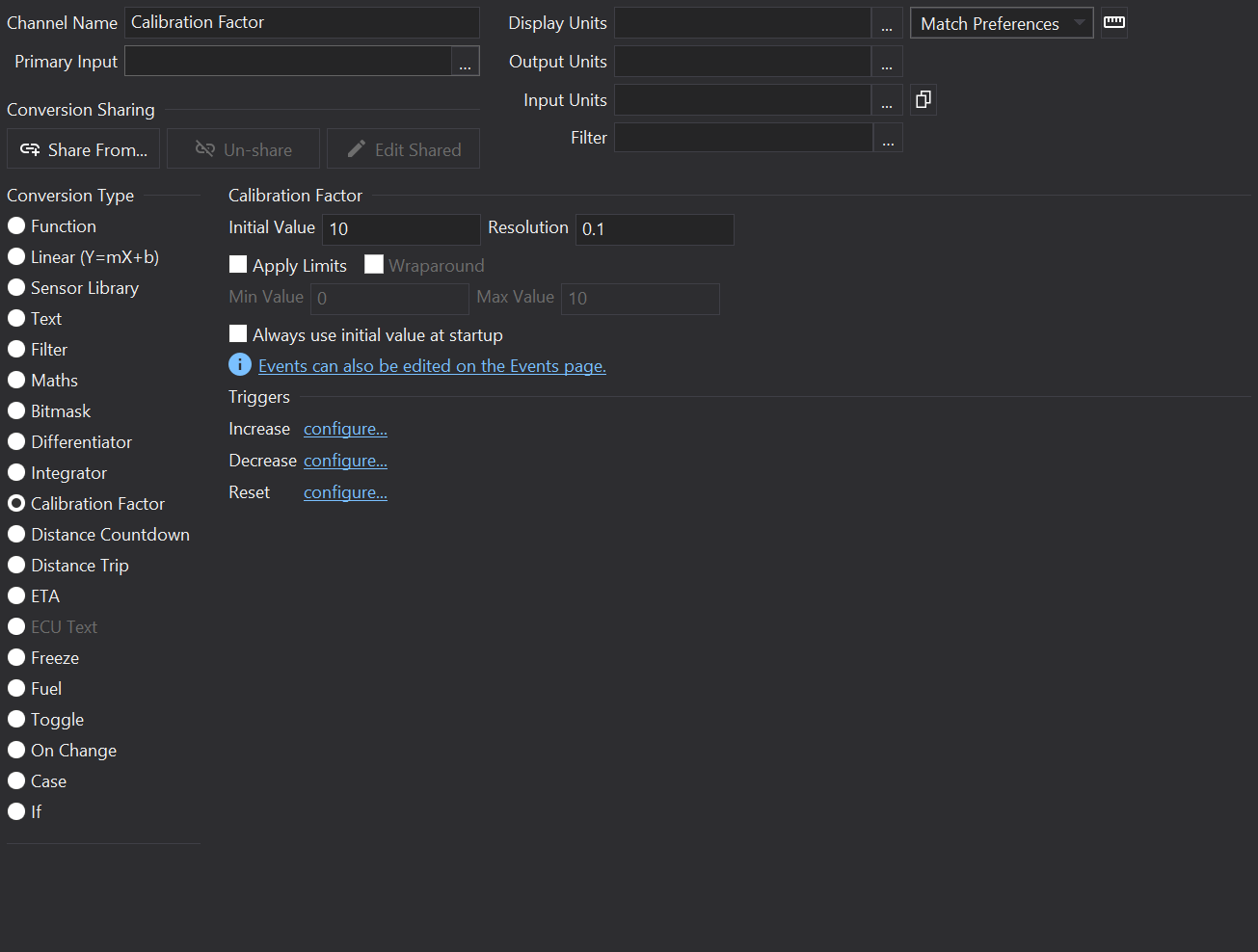
Calibration Factor Channel
Overview
Calibration Factor channels allow a programmable value to be created that can be linked into the events system to allow end users to set a new value on the display itself.
This can be used as a calibration factor or for storing initial fuel values for example.
Settings
Initial Value
The display will use this value whenever a new setup has been programmed.
If the output has not been added to the monitor page, then the output will be reset to this value whenever it is not shown.
Always use initial value at startup
If “Always use initial value at startup” is checked then the calibration factor will not be saved in non-volatile memory during power-off of the display.
If the value should be persistent when the display is switched off, then the output MUST be added to the Monitored Channels
.
Resolution
This is the amount the value is changed by in response to the Increase and Decrease events.
Apply Limits
If ticked then the display prevents the value from exceeding the Min Value or Max Value limits.
Wraparound
If limits are specified then the Wraparound option is available. Check Wraparound to make the calibration value go back to Min Value after increasing the value beyond Max Value (and also in the opposite direction).
Configures the event for increasing the calibration factor by the Resolution value.
Decrease
Configures the event for decreasing the calibration factor by the Resolution value.
Reset
Configures the event for resetting the calibration factor value to Initial Value.
Supported By Displays
Display
Supported?
CD34
Yes
LDS4
Yes
CD32
Yes
LDS35
No
LDS35_L
No
CD6-43
Yes
GLW-43
Yes
LFRW-43
Yes
ZDU-L
Yes
ZDU-P
Yes
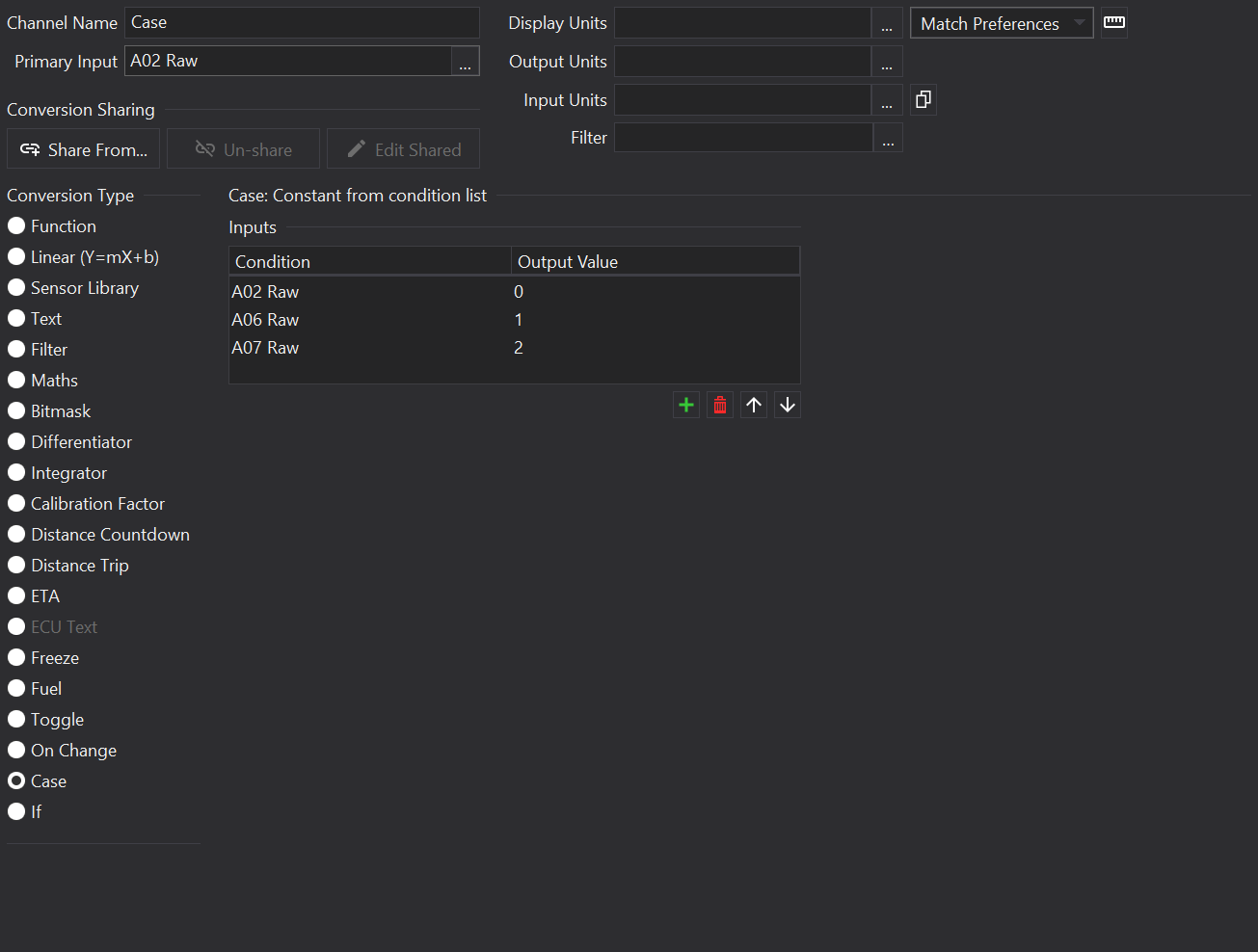
Case Channel
Overview
Checks through a list of input channels until a non-zero (true) input is found and outputs a value corresponding to that input.
Conditions
The condition list is in priority order - highest priority first; the case channel checks each Condition in list order in turn until a true condition (i.e. the value of the output is greater than 0) is found. This then results in the corresponding Output Value from the channel.
The case sensor is useful for making an output for use as the selector input in a bitmap selector.
Use the and buttons to the bottom right of the list to add or remove rows from the list.
The priority of items may be adjusted with the and buttons.
Supported By Displays
Display
Supported?
CD34
Yes
LDS4
Yes
CD32
Yes
LDS35
Yes
LDS35_L
Yes
CD6-43
Yes
GLW-43
Yes
LFRW-43
Yes
ZDU-L
Yes
ZDU-P
Yes
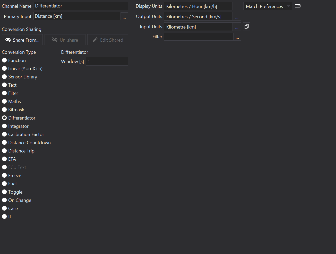
Differentiator Channel
Overview
Differentiator channels are used to create an output that is the differential of an input with respect to time; i.e. the gradient or rate of change of the input value.
Differentiation is the inverse of integration (see Integrator Channel
). Given an input like Distance Travelled, the rate of change may be computed to give an approximation of the Speed.
Options
Window[s]
Computing differentials using the first difference alone can result in a very noisy looking signal.
The average slope over the last Window seconds is therefore computed.
Acceptable values are between 0.1 and 2.0 seconds.
Higher numbers will produce a smoother, more filtered output but with a slower response time.
Supported By Displays
Display
Supported?
CD34
Yes
LDS4
Yes
CD32
Yes
LDS35
Yes
LDS35_L
Yes
CD6-43
Yes
GLW-43
Yes
LFRW-43
Yes
ZDU-L
Yes
ZDU-P
Yes
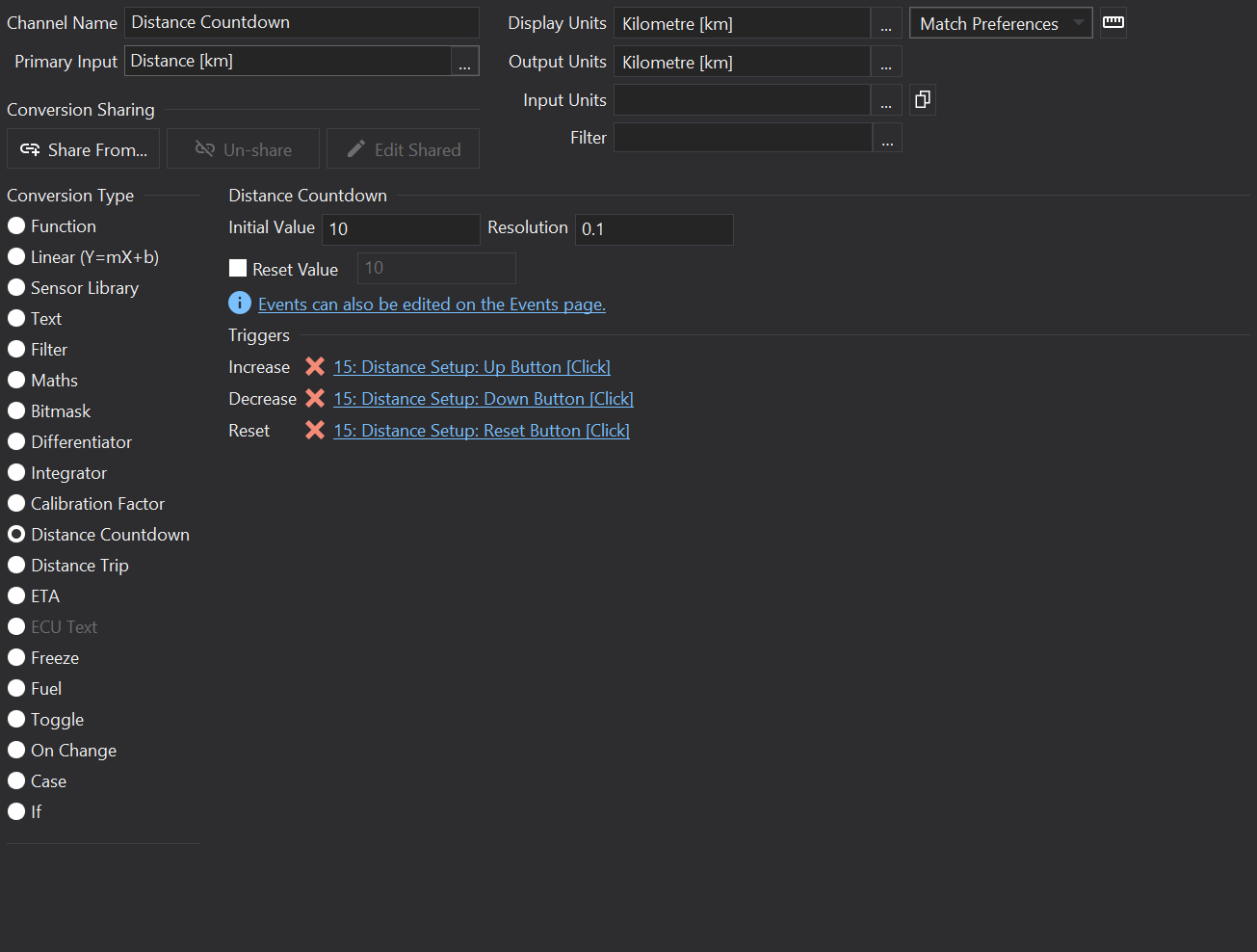
Distance Countdown Channel
Overview
Distance Countdown Factor channels allow a programmable distance count-down value to be created that can be linked into the events system to allow end users to set a new value on the display itself and reset the countdown value with an event.
Settings
Initial Value
When a Reset event is received, the output shall be reset to Initial Value.
Reset Value
If Reset Value is checked then the display will use this value whenever a new setup has been programmed.
If the output has not been added to the monitor page, then the output will be reset to this value whenever it is not shown.
Resolution
This is the amount the value is changed by in response to the Increase and Decrease events.
Configures the event for increasing the Initial Value by the Resolution value.
Decrease
Configures the event for decreasing the Initial Value by the Resolution value.
Reset
Configures the event for resetting the output value to Initial Value.
Supported By Displays
Display
Supported?
CD34
Yes
LDS4
Yes
CD32
Yes
LDS35
No
LDS35_L
No
CD6-43
Yes
GLW-43
Yes
LFRW-43
Yes
ZDU-L
Yes
ZDU-P
Yes
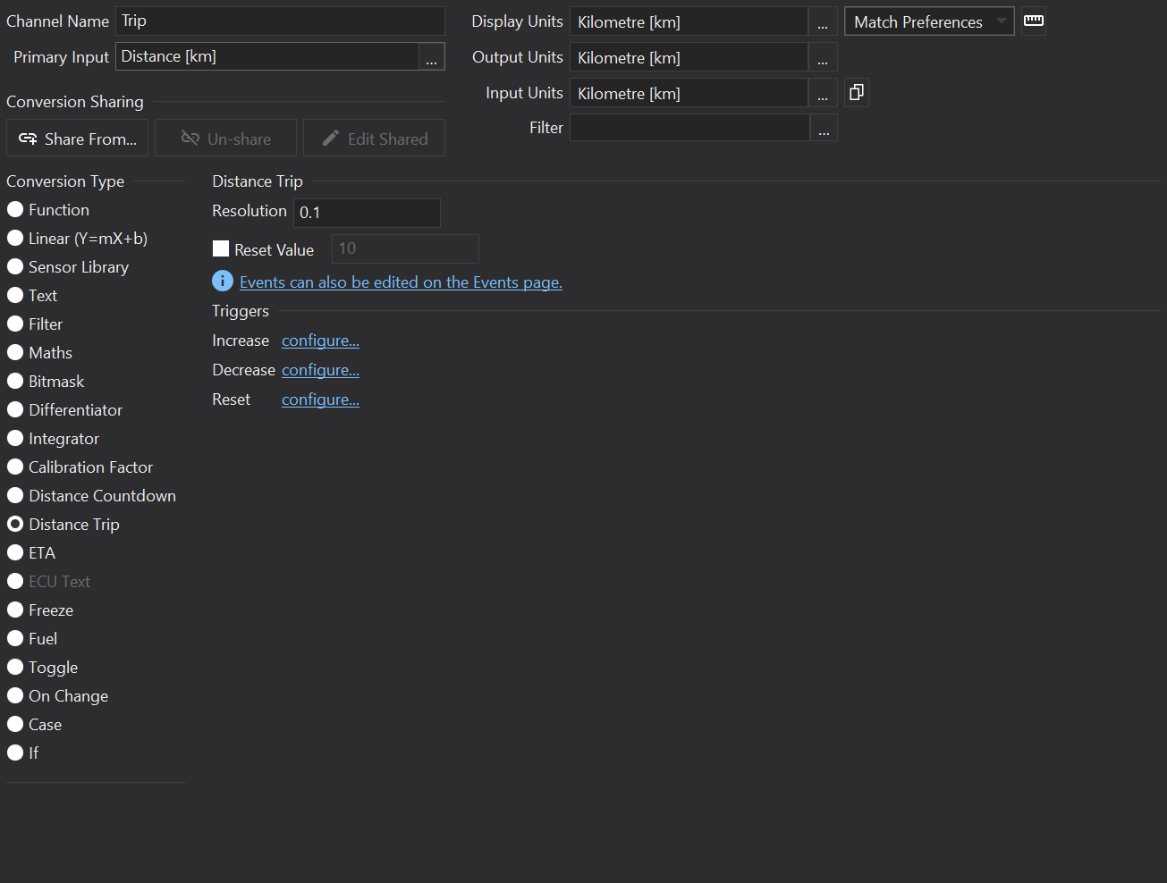
Distance Trip Channel
Overview
Distance Countdown Factor channels allow a programmable distance count-down value to be created that can be linked into the events system to allow end users to set a new value on the display itself and reset the countdown value with an event.
Settings
Reset Value
If Reset Value is checked then the display will use this value whenever a new setup has been programmed.
Resolution
This is the amount the value is changed by in response to the Increase and Decrease events.
Configures the event for increasing the Output Value by the Resolution value.
Decrease
Configures the event for decreasing the Output Value by the Resolution value.
Reset
Configures the event for resetting the output value to zero.
Supported By Displays
Display
Supported?
CD34
Yes
LDS4
Yes
CD32
Yes
LDS35
No
LDS35_L
No
CD6-43
Yes
GLW-43
Yes
LFRW-43
Yes
ZDU-L
Yes
ZDU-P
Yes
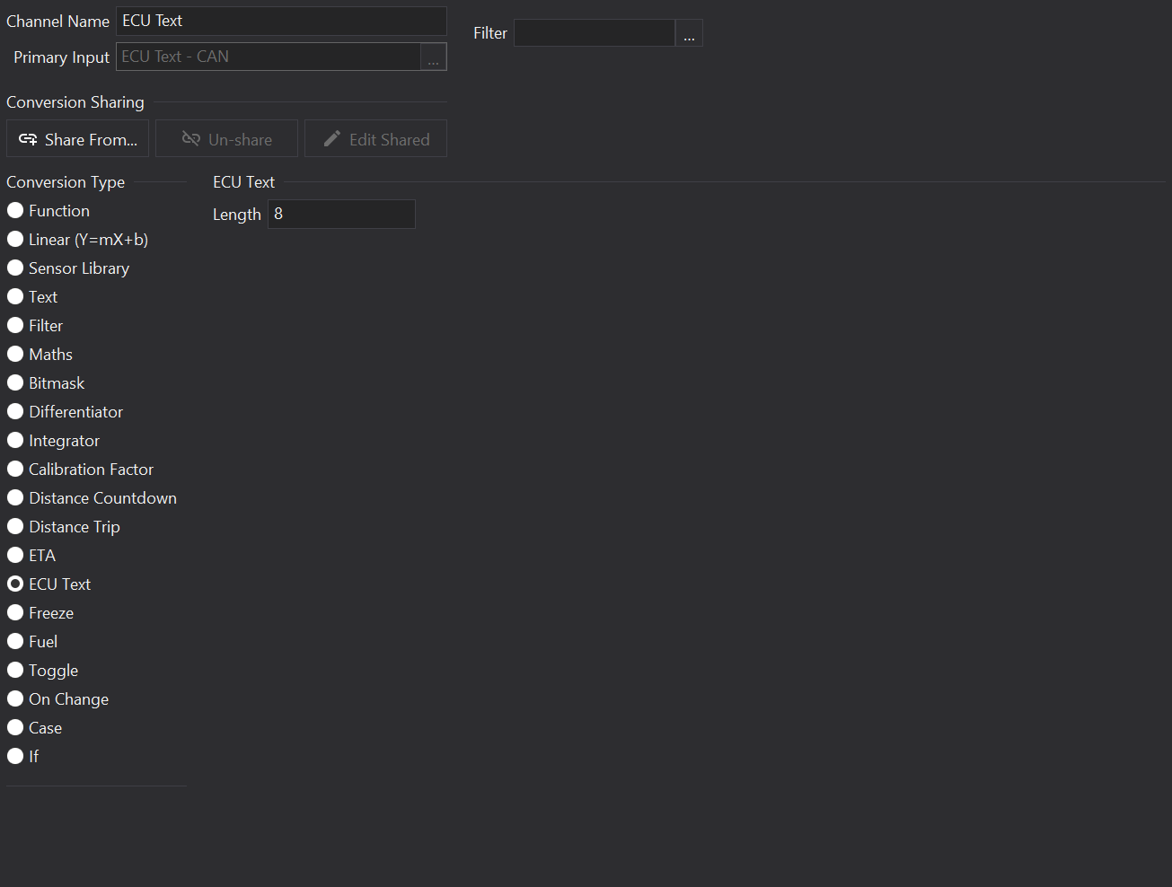
ECU Text Channel
Overview
ECU Text channels are used to obtain a text string (such as a calibration name) from a connected ECU.
Info
The ECU Text channel type may only be selected on channels that come directly from a raw CAN source.
Options
Length
The length of the string to read. Characters are read one-by-one from input value updates, typically this would be a single byte in a CAN message.
Typically strings would come from an ECU in response to a CAN Request
.
Supported By Displays
Display
Supported?
CD34
Yes
LDS4
Yes
CD32
Yes
LDS35
Yes
LDS35_L
Yes
CD6-43
Yes
GLW-43
Yes
LFRW-43
Yes
ZDU-L
Yes
ZDU-P
Yes
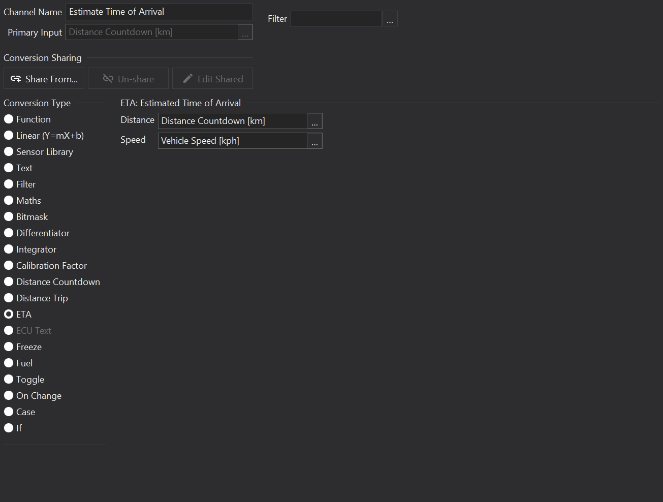
ETA Channel
Overview
ETA channels are used to compute an estimated time of arrival.
ETA channels output a time value and any gauges must have an appropriate time format specified.
Options
Distance
Select a channel with the distance remaining to the destination. The channel should have appropriate units, see Conversion below.
Speed
Select a channel with the vehicle speed. The channel should have appropriate units, see Conversion below.
Conversion
The ETA channel computes the time, in seconds using the equation:
('Distance' * 3600) / 'Speed'
This is then converted to a time value.
Since there are 3600 seconds in an hour, it is expected that the speed is in distance/hour.
So the following options are viable for the input units of the Distance and Speed channels:
Distance [km], Speed [kph]
Distance [mi], Speed [mph]
Supported By Displays
Display
Supported?
CD34
Yes
LDS4
Yes
CD32
Yes
LDS35
Yes
LDS35_L
Yes
CD6-43
Yes
GLW-43
Yes
LFRW-43
Yes
ZDU-L
Yes
ZDU-P
Yes
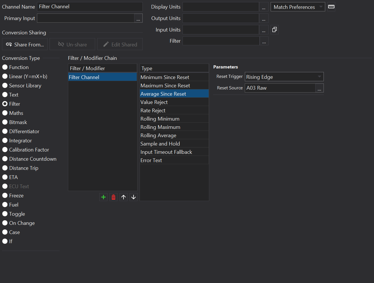
Filter Channel
Overview
Filter channels can be configured to apply a chain of filters to the Primary Input channel.
Adding / Removing Filters
Use the and buttons to the bottom right of the Filter/Modifier list to add or remove filters from the list. The first item is the Filter Channel itself and can’t be removed.
Chained Filters
When there are multiple filters in a chain, Dash Design will insert hidden ‘modifier’ channels into the setup.
If the channel is used as the input to another output or a gauge then references shall be updated so that value at the end of the filter chain is routed to the output or gauge.
Filters
Minimum Since Reset
Outputs the minimum value of valid input values since the display was started / the filter was reset.
See Reset Triggers for details on the Reset Trigger and Reset Source options.
Maximum Since Reset
Outputs the maximum value of valid input values since the display was started / the filter was reset.
See Reset Triggers for details on the Reset Trigger and Reset Source options.
Average Since Reset
Outputs the average value of valid input values since the display was started / the filter was reset.
See Reset Triggers for details on the Reset Trigger and Reset Source options.
Value Reject
Rejects any input values that are below Minimum or above Maximum.
If out of range inputs are received then the value is not passed on to derived outputs or gauges.
Rate Reject
A filter that limits the rate of change of the input channel.
Data that changes faster than the rate limit is discarded. Called ‘Rate Filter’ in prior versions.
Rolling Minimum / Rolling Maximum / Rolling Average
Outputs the minimum/maximum/average value of the input value over a time window.
Update Period [ms]
Frequency at which the filter is calculated and will produce a value.
Increasing the update period will reduce memory requirements since the display must store less samples in the given time window.
Rolling Period [ms]
Range over which the rolling function is calculated (the window size).
Avoid excessively large windows with short update periods as these will require large amounts of memory in the display.
If the memory required for the window exceeds available resources, then the display setup may not function correctly.
Sample And Hold (Resample)
A filter that takes a single channel value sample and outputs that value for a predetermined time, before another sample is taken and output.
S&H Update Period [ms]
Frequency at which the input value is resampled.
Input Timeout Fallback
A filter that watches to see if an input channel is still being updated and if not, then a default value is sent in it’s place.
Typically used to define a replacement channel value when a CAN channel ceases to arrive as expected rather than just showing the last CAN value received.
Fallback Value
Value to output if the input times-out.
Timeout Value
Timeout, in milliseconds. If no value received after this period, the fallback value will be shown.
Error Text
Checks if a value is out of range to produce error text when in the out of range condition.
Comparison Value
Value for logic comparison with the input value (NOT Error Input).
Comparator
Logical comparison operator for comparing input value with the input value, as in:
'input value' <comparator> <comparison value>
e.g.
'input value' < 5
Error Text Option
Text that should be output to gauges if the error condition is active.
Error Input
Input channel that if non-zero, shall be used to put the channel into the error condition.
If an Error Input and a condition are specified then the result is the logical OR of the two conditions.
Reset Triggers
Many filters offer a Reset Trigger. This is specified in conjunction with a Reset Source.
Reset Source
Input Channel to reset the filter. The Reset Trigger option specifies how the Reset Source value is interpreted.
Reset Trigger
Select the condition under which the Reset Source should trigger a reset of the filter.
Any Edge
Any change in value of Reset Source shall reset the filer.
Falling Edge
Reset the filter when Reset Source reduces in value.
Rising Edge
Reset the filter when Reset Source increases in value.
Level: OFF
Reset the filter when Reset Source is zero.
Level: ON
Reset the filter when Reset Source is not zero.
Supported By Displays
Display
Supported?
CD34
Yes
LDS4
Yes
CD32
Yes
LDS35
Yes
LDS35_L
Yes
CD6-43
Yes
GLW-43
Yes
LFRW-43
Yes
ZDU-L
Yes
ZDU-P
Yes
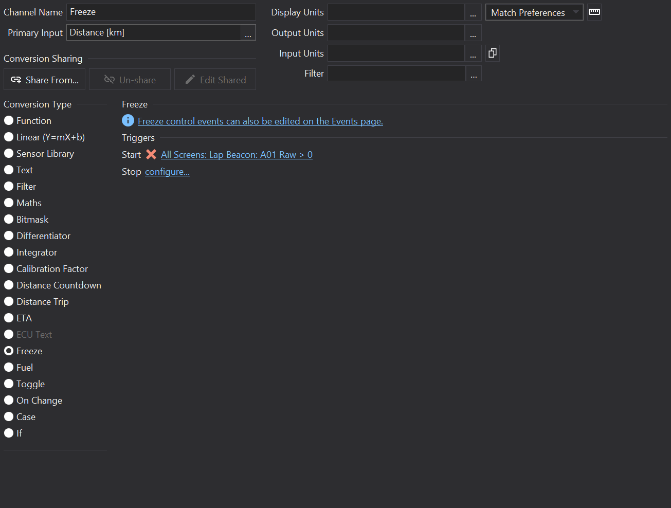
Freeze Channel
Overview
Outputs the Primary Input value as-is. In response to start/stop events, the output is be held at the input value when the freeze state was entered.
This is useful for example when freezing values at stage end in rallying.
Events
Start
Click the link to select an event that should put the channel into the freeze state.
Stop
Click the link to select an event that should take the channel out of the freeze state.
Supported By Displays
Display
Supported?
CD34
Yes
LDS4
Yes
CD32
Yes
LDS35
No
LDS35_L
No
CD6-43
Yes
GLW-43
Yes
LFRW-43
Yes
ZDU-L
Yes
ZDU-P
Yes
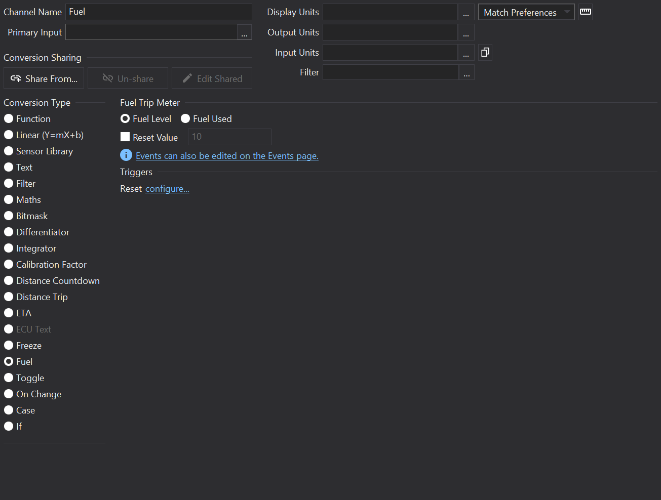
Fuel Channel
Overview
Fuel used trip meter - outputs the amount of a resource (e.g. fuel) used / remaining.
The Primary Input value is an absolute value of the used resource.
Effectively the Fuel Channel outputs the change in value since the first value is received or since a reset event.
Options
Fuel Level
Count down from the initial value to zero.
Fuel Used
Count up from the initial value.
Reset Value
If not checked then the reset value will be the initial input value.
Triggers
Reset
Configurable event to reset to the initial value or, if specified, the reset value.
Supported By Displays
Display
Supported?
CD34
Yes
LDS4
Yes
CD32
Yes
LDS35
No
LDS35_L
No
CD6-43
Yes
GLW-43
Yes
LFRW-43
Yes
ZDU-L
Yes
ZDU-P
Yes
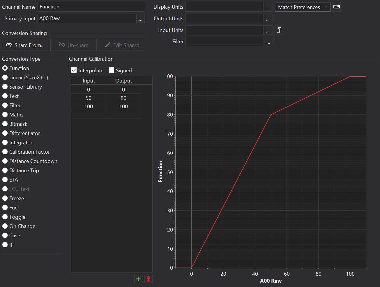
Function (Lookup Table) Channel
Overview
Function tables are used for non-linear scaling; they ’look up’ the value of the ‘Primary Input’ in the table and result in the corresponding output value.
Settings
Interpolate
If the input falls between two values, linear interpolation is used to derive the output value.
Otherwise, the output will be stepped. This can be useful for resistive ladder type switches for e.g. page selector inputs.
Signed
If ‘signed’ is checked then raw input values are treated as twos-complement numbers.
Table Values
Editing
Enter values into the table by typing. There is an empty row at the end of the table for adding new values.
Rows may be inserted between other rows by selecting ‘Insert’ from the context menu (right-click on the grid).
The and buttons to the bottom right of the table may be used to add or remove rows.
Tip
Use the TAB key and Shift-TAB to navigate between the table editor cells using the keyboard.
Clipboard
Table values may be copied to / pasted from the clipboard in a spreadsheet compatible format. Right-click on the grid to show the context menu and select copy/paste.
Supported By Displays
Display
Supported?
CD34
Yes
LDS4
Yes
CD32
Yes
LDS35
Yes
LDS35_L
Yes
CD6-43
Yes
GLW-43
Yes
LFRW-43
Yes
ZDU-L
Yes
ZDU-P
Yes
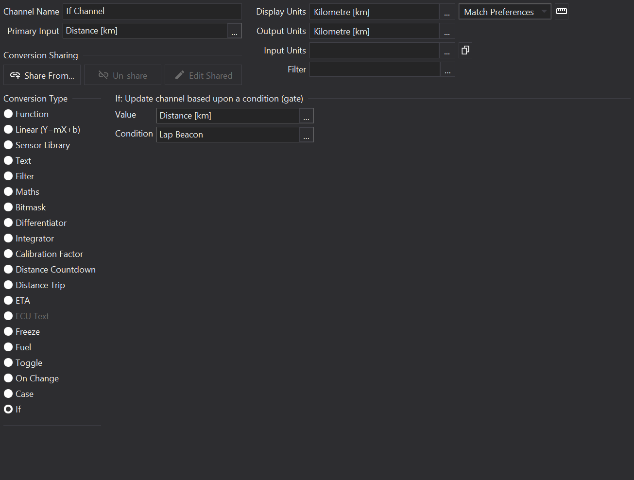
If Channel
Overview
The If Channel uses two inputs. It passes the specified input through to the output if the conditional input is true non-zero.
Options
Value
The Primary Input, the value to pass through if the Condition input is non-zero.
Condition
An input channel that if non-zero allows the primary input value to be passed on to any derived outputs or gauges.
Supported By Displays
Display
Supported?
CD34
Yes
LDS4
Yes
CD32
Yes
LDS35
Yes
LDS35_L
Yes
CD6-43
Yes
GLW-43
Yes
LFRW-43
Yes
ZDU-L
Yes
ZDU-P
Yes
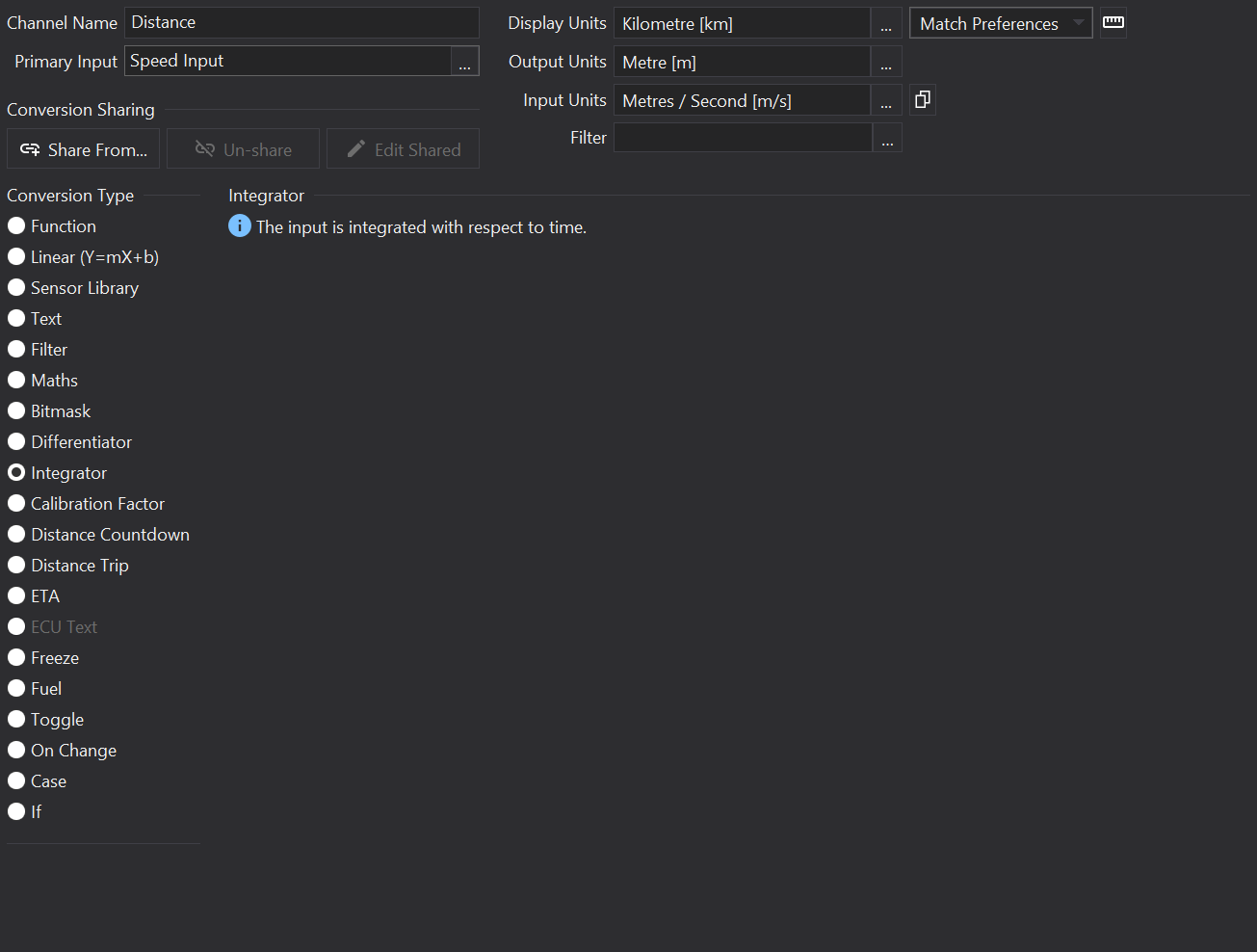
Integrator Channel
Overview
Integrator channels perform integration of the Primary Input, with respect to time (in seconds) to produce an output.
For example, it can be used to produce a distance output from a speed input.
Integration is effectively the area under a graph of the Primary Input on the y-axis plotted against time, in seconds, on the x-axis.
Primary Input Requirements
Integrator Channels require the Primary Input to be a rate per second (e.g. [m/s] or [m/s/s]).
Input units may be specified on the channel to ensure that an appropriate units conversion is made if the Primary Input is not with respect to seconds.
For example, if Primary Input is in units of [rpm], the input units could be set to [rps] to convert to revolutions per second for correct integration, producing a value of ‘revolutions’.
Supported By Displays
Display
Supported?
CD34
Yes
LDS4
Yes
CD32
Yes
LDS35
Yes
LDS35_L
Yes
CD6-43
Yes
GLW-43
Yes
LFRW-43
Yes
ZDU-L
Yes
ZDU-P
Yes
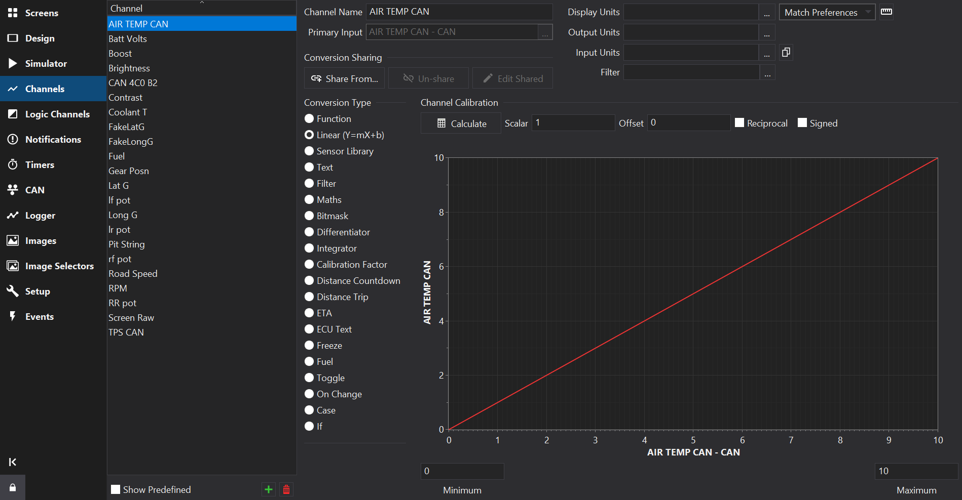
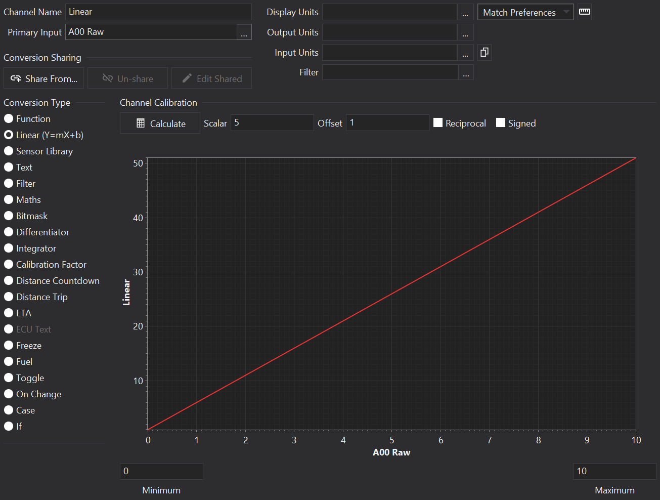
Linear (Scalar) Channel
Overview
This is one of the most commonly used channel types. The channel is scaled using a linear scaling equation y = mx + c - i.e a multiplier and offset.
Settings
Scalar
The multiplier value (m in y = mx + c).
Offset
Added to the value after applying the multiplier (c in y = mx + c).
Signed
If ‘signed’ is checked then raw input values are treated as twos-complement numbers.
Reciprocal
If ‘reciprocal’ is checked then the scaling equation takes the form y = (1 / x) * scalar + offset. If the input value is zero then the result will be the special floating point value NaN (Not a Number).
Graph
The graph shows the scaling relationship.
Minimum
Sets the minimum value to show on the X-axis of the graph. This has no effect on the setup when running on the display.
Maximum
Sets the maximum value to show on the X-axis of the graph. This has no effect on the setup when running on the display.
Calculation from Reference Values
If a pair of reference values for input vs output are available (e.g. from a sensor data-sheet), click the Calculate button () and enter in the values. Clicking OK will compute the scalar and offset required to fit the pair of points.
Supported By Displays
Display
Supported?
CD34
Yes
LDS4
Yes
CD32
Yes
LDS35
Yes
LDS35_L
Yes
CD6-43
Yes
GLW-43
Yes
LFRW-43
Yes
ZDU-L
Yes
ZDU-P
Yes
Maths Channel
Overview
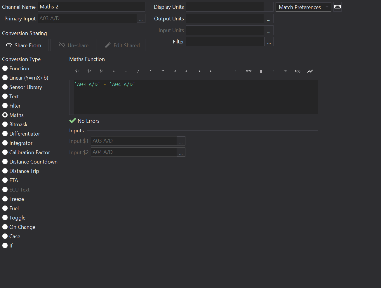
Maths channels can be used to calculate values from one or more inputs using arithmetic and functions.
The equation entered for a maths channel is referred to as a ‘script’.
Script Entry
Type in the Maths Function area to enter in your script.
Tip
Press Ctrl-Space in the script editor to show function / constant autocomplete.
Below the script entry area, any errors in the script will be shown.
Above the script area are buttons for inserting channels, functions, operators and constants.
Whilst it is generally quicker to type scripts in by hand, the buttons offer a reminder of what’s available.
Input Variables
Input variables may be specified in maths scripts in the form $N where N is a number, e.g. $1 or $5. Up to 64 input variables may be specified.
If input variables are used then the inputs may be selected underneath the script entry area.
For example, to multiply two input variables together, you could write:
$1 * $2
Inline Channels
As an alternative to Input variables, channels can be specified directly in maths scripts using the channel name in single quotation marks.
e.g.
'Analog 01'
When typing a single quote character in the script editor, a list of channels will be shown for auto-completion.
Comments
Comments can be inserted in scripts and start with a # character. They continue to the end of the line. Scripts may span over multiple lines.
# This is a comment
Operators
Operator
Precedence
Description
()
1
Parenthesis for grouping expressions, e.g. ('x' + 'y') * 4
**
2
Exponentiation (x ** y => xy)
*
3
Multiplication
/
3
Division
%
3
Modulo (remainder of integer division)
+
4
Addition
-
4
Subtraction
As with normal algebra, multiplication of terms takes precedence over addition and will be applied first. If the precedence is not clear, it is recommended to group expressions using parenthesis.
e.g. in the expression:
1 + 2 * 3 # Multiplication takes precedence over addition so 2 is multiplied by 3 before adding 1.
Operators at the same level of precedence are evaluated left-to-right.
Constants
Function
Description
E
Eulers number e, 2.718281…
PI
Pi (π), 3.141592…
PHI
Golden Ratio, Phi (φ), 1.618033…
true
Boolean 1.
false
Boolean 0.
Functions
Function
Description
abs(x)
Returns the absolute value of ‘x’,
exp(x)
Returns the natural exponential of ‘x’, ex.
log10(x)
Returns the base 10 logarithm of ‘x’.
ln(x)
Returns the natural (base e) logarithm of ‘x’.
min(x1, x2 …xN)
Returns the minimum value of x1…xN.
max(x1, x2 …xN)
Returns the maximum value of x1…xN.
pow(x, y)
Returns x raised to the power of y; xy.
sgn(x)
Returns the 1 if ‘x’ is positive, -1 if ‘x’ is negative and 0 if ‘x’ is zero.
sqr(x)
Returns the square of ‘x’.
sqrt(x)
Returns the square root of ‘x’.
Trigonometric Functions
Function
Description
acos(x)
Returns the arc-cosine (inverse cosine) of ‘x’, in radians.
asin(x)
Returns the arc-sine (inverse sine) of ‘x’, in radians.
atan(x)
Returns the arc-tangent (inverse tangent) of ‘x’, in radians.
cos(x)
Returns the cosine of ‘x’ (in radians).
sin(x)
Returns the sine of ‘x’ (in radians).
tan(x)
Returns the tangent of ‘x’ (in radians).
Supported By Displays
Display
Supported?
CD34
Yes
LDS4
Yes
CD32
Yes
LDS35
Yes
LDS35_L
Yes
CD6-43
Yes
GLW-43
Yes
LFRW-43
Yes
ZDU-L
Yes
ZDU-P
Yes
On Change Channel
Overview
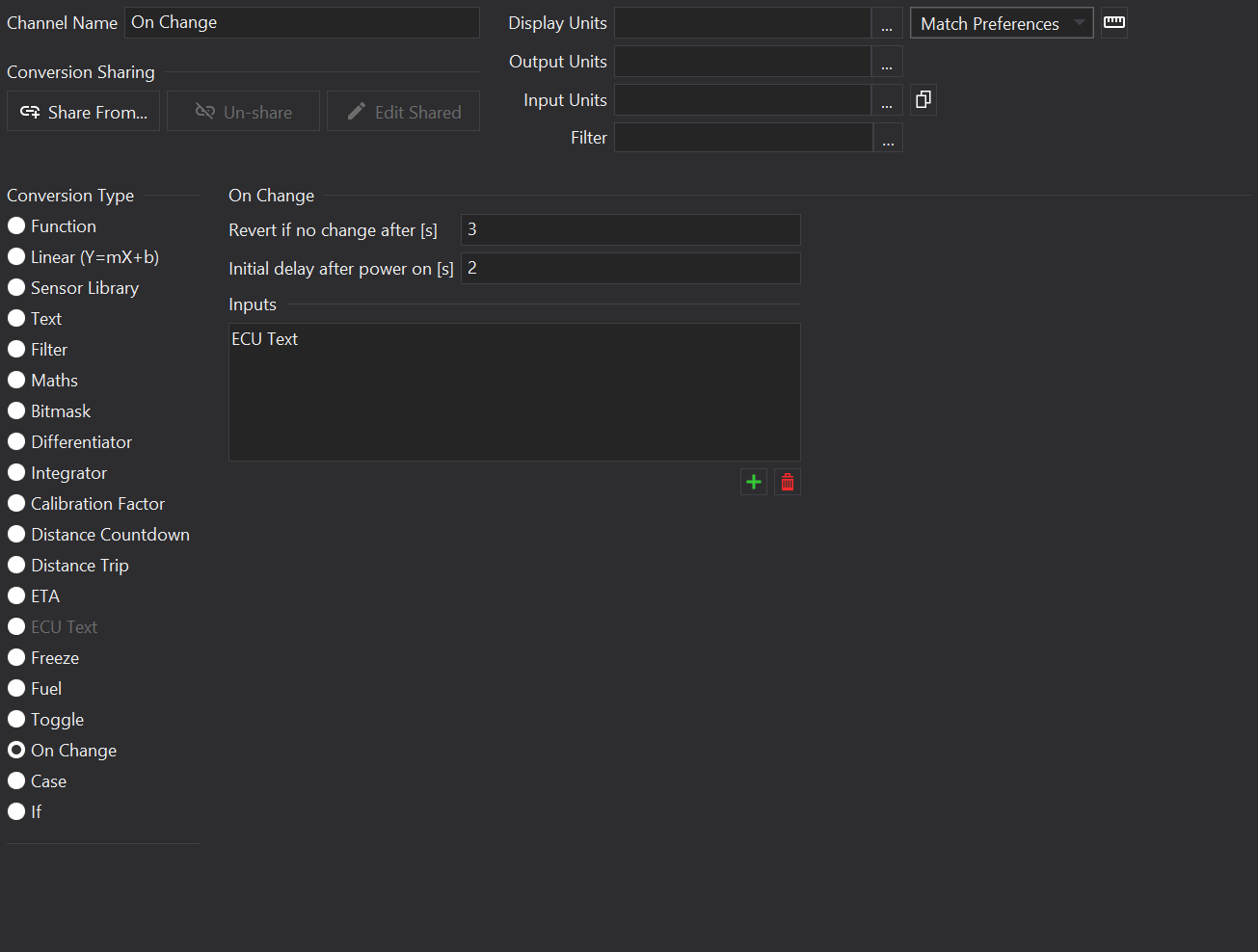
On Change Channels are used to monitor multiple input channels for changes.
If any of the input channels change, the value of the On Change output changes from 0 to 1.
This is useful for example, for monitoring mode switches; when one of the modes changes, the On Change output can be used as an event to trigger a jump to a page showing more information about the changing mode.
Options
Revert if no change after [s]
Once triggered, the On Change Revert shall be triggered after the Revert timeout has elapsed.
Initial delay after power on [s]
Following a power-up or system reset, the Initial Delay prevents the On Change channel from producing a value.
Remarks
When an On Change output is created, a hidden On Change Revert channel is created using the name of the On Change output with a _Revert suffix. This output is a logical not of the On Change channel and can be used to revert back to the original screen once the output has stopped changing.
Supported By Displays
Display
Supported?
CD34
Yes
LDS4
Yes
CD32
Yes
LDS35
Yes
LDS35_L
Yes
CD6-43
Yes
GLW-43
Yes
LFRW-43
Yes
ZDU-L
Yes
ZDU-P
Yes
Sensor Library Channel
Overview
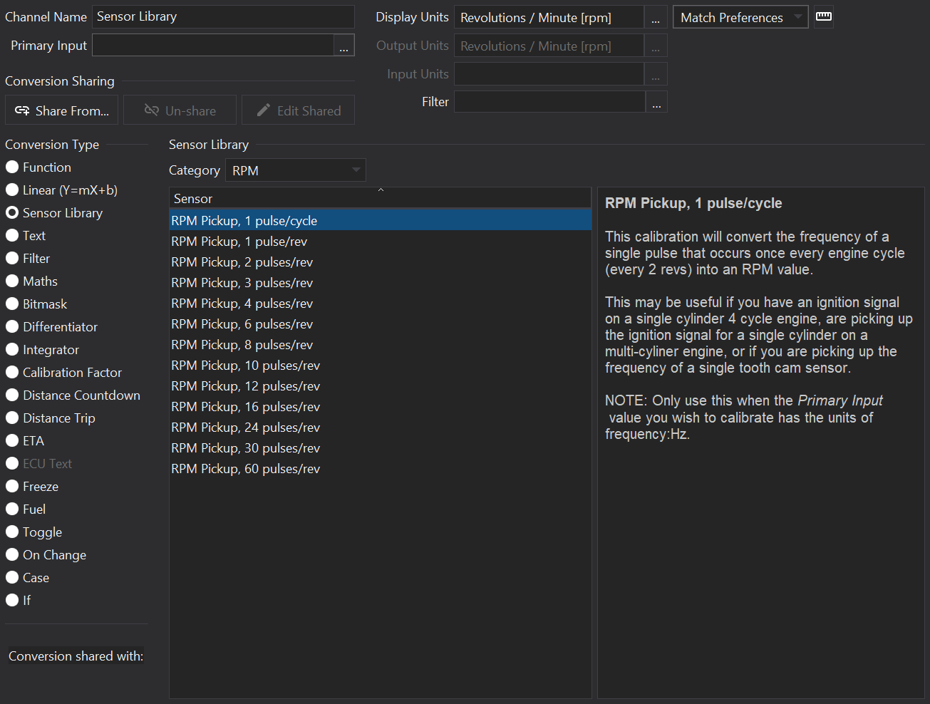
Sensor Library Channels provide a library of sensor types that may be selected from.
Info
The sensor library channel will only be available if a sensors.library file is installed in the application’s program files directory.
Sensor Selection
Select a category from the drop-down box and the list of sensors will be filtered according to type (e.g. Pressure or RPM).
Select a sensor in the Sensor List to apply the scaling.
To the right of the sensor list, a description of the sensor will be shown, if available in the library.
Sensor Library File
The sensors.library file can be provided in XML format:
<?xml version="1.0" encoding="UTF-8" standalone="yes" ?><sensor_library><scalarcategory="Pressure"name="Type 1"multipler="3.5"offset="-1"input_units="voltage:V"units="pressure:psi"><notes><v:long_varstr><!-- HTML description --></v:long_varstr></notes></scalar><scalarcategory="Pressure"name="Type 2"multipler="2.5"offset="-0.5"input_units="voltage:V"units="pressure:psi"><notes><v:long_varstr><!-- HTML description --></v:long_varstr></notes></scalar><functioncategory="AFR"name="AFR Gauge Type 1"input_units="voltage:V"units="afr:LA"><notes><v:long_varstr><!-- HTML description --></v:long_varstr></notes><ft_iopairfti_double="0.00"fto_double="0.6"/><ft_iopairfti_double="2.00"fto_double="1.0"/><ft_iopairfti_double="3.00"fto_double="1.1"/><ft_iopairfti_double="4.00"fto_double="1.2"/><ft_iopairfti_double="5.00"fto_double="1.4"/></function></sensor_library>
Text Channel
Overview
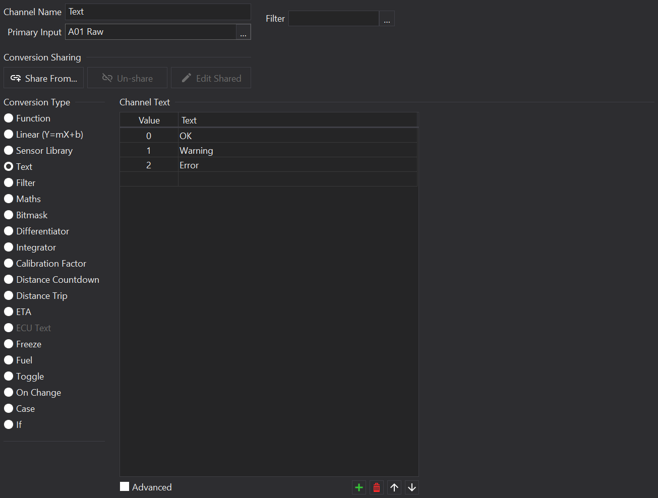
Text Channels look-up a textual representation for a given input value.
If the input has distinct values for each possible text value (i.e. an enumeration) then a list of value => text may be specified.
If the input has multiple bits to indicate active states then a set of masks with priority may be specified (Advanced Mode).
Adding / Removing Items
Use the and buttons to the bottom right of the list to add or remove rows.
There is also a blank row at the end of the list - entering values in the blank row will append a new entry.
The order of items may be adjusted with the and buttons.
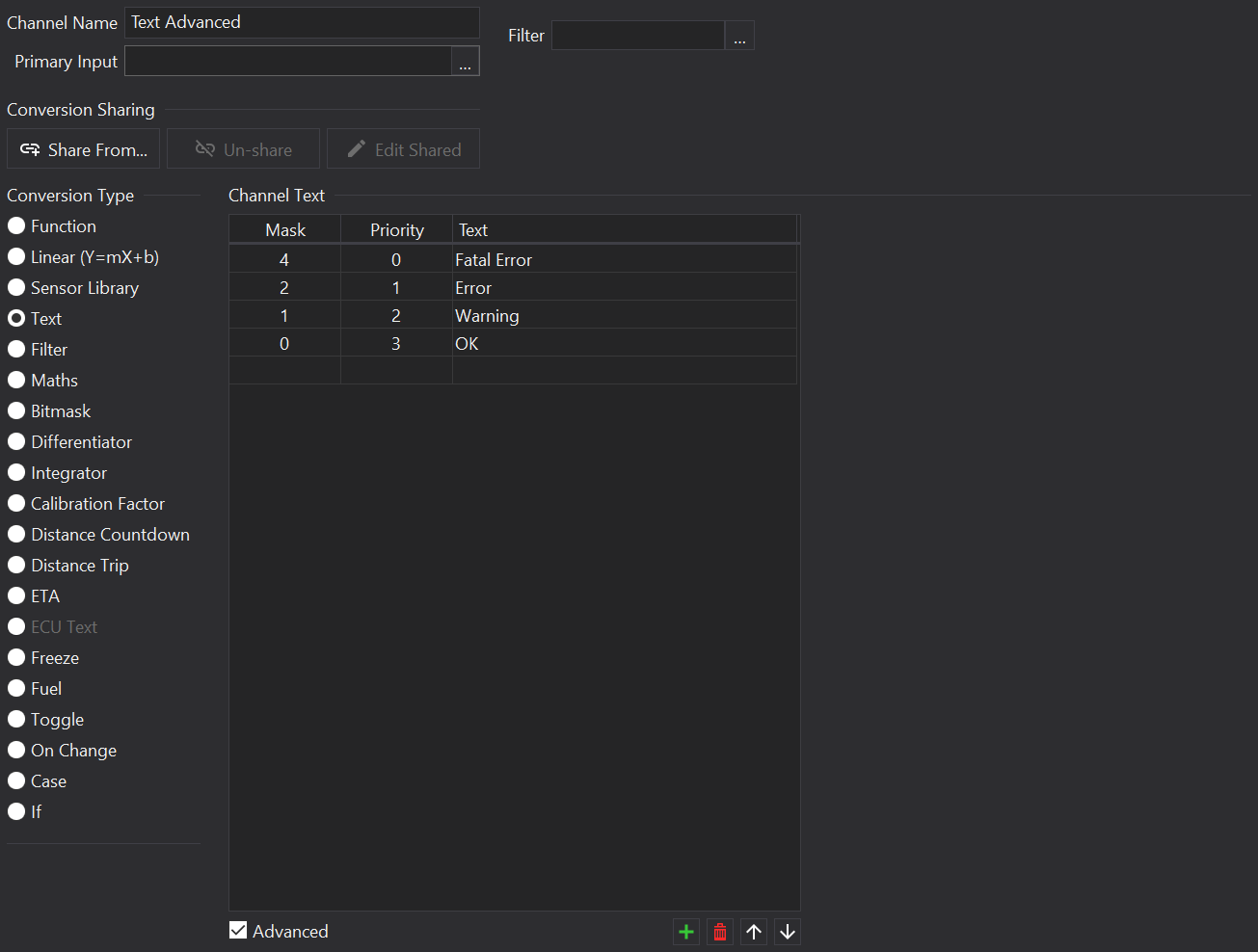
Advanced Mode
In advanced mode, the list has 3 columns:
Bitmask
Value to mask (logical AND) with the input and if all the bits are set then the item is active.
Priority
If any items are active then the one with the ‘highest’ priority shall be shown. Lower numbers have a higher priority (e.g. Priority 0 overrides Priority 1).
Text
The text to display if the item is active.
Supported By Displays
Display
Supported?
CD34
Yes
LDS4
Yes
CD32
Yes
LDS35
Yes
LDS35_L
Yes
CD6-43
Yes
GLW-43
Yes
LFRW-43
Yes
ZDU-L
Yes
ZDU-P
Yes
Toggle Channel
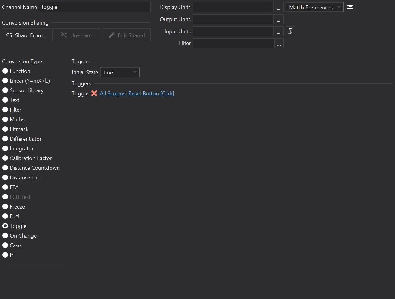
Overview
Toggle Channels switch between 0 and 1 when a toggle event is received.
For example, it can be used to toggle the display between operating in MPH and KPH in response to a button push.
Options
Initial State
The initial output value of the channel before any toggle events have been received.
Triggers
Toggle
Click on the link to select an event that should cause the Toggle Channel to change state.
 button to clone the input units from the Primary Input.
 button is show to the right of the drop-down box to open the Unit Preferences. The preferences are also available from the menu action , see Unit Preferences
for more details.
button is show to the right of the drop-down box to open the Unit Preferences. The preferences are also available from the menu action , see Unit Preferences
for more details. button to add a new channel, and the
  button to remove the selected channel(s).
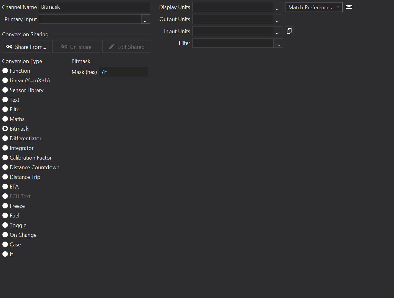
 ) and enter in the values. Clicking OK will compute the scalar and offset required to fit the pair of points.