CAN Tab
Overview
The CAN Tab provides configuration of CAN channels and, if supported by the display, CAN message transmission (CAN Tx).
There are further sub-tabs within the CAN Tab:
The CAN Tab provides configuration of CAN channels and, if supported by the display, CAN message transmission (CAN Tx).
There are further sub-tabs within the CAN Tab:
Many ECUs and modules are provided with a Signal Database (DBC) file which defines the CAN IDs and scaling factors that are output by nodes (e.g. ECUs) on the CAN network.
GEMS GWv4 software can generate a dbc file for the CAN telemetry output for any GEMS CAN enabled ECU.
Dash Design supports importing DBC files and this greatly simplifies the initial setup of the display. As well as importing the CAN ID, start bit, length etc for each channel, it also imports scaling factors and creates the outputs required for use by any of the display gauges.
To import a DBC file into the current setup, click the Import… button in the CAN Receive editor.

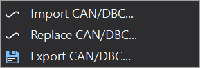
Select “Import CAN/DBC…” to add to the current list of signals.
Select the DBC file to open from the file dialog. The DBC Import dialog will then be shown:
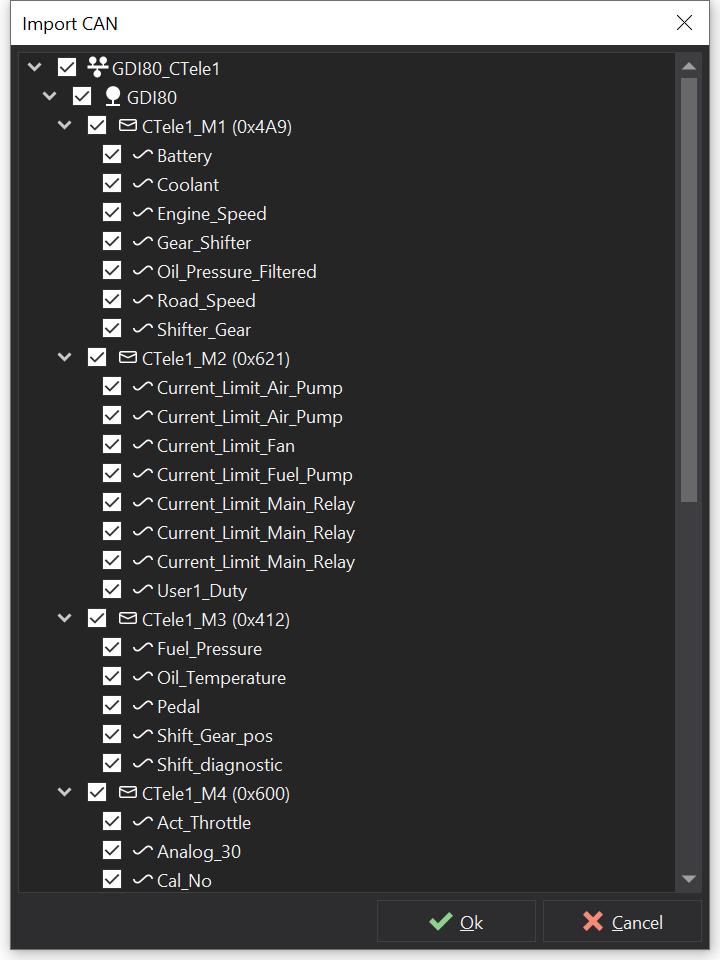
The dialog shows a tree view with the network name as the parent.
Below this is a list of nodes on the network - in the above example, there is only one node, “GDI80”.
Below this is a list of messages with their IDs (eg “CTele1_M1 (0x4A9)”). If the message list is expanded, a list of the signals or channels on this message is shown (eg “Engine_Speed”, “Coolant” etc).
Any item with a tick next to it will be imported.
By default, everything is selected to be imported. If there are some signals, messages or nodes that are not needed, unchecking these items will prevent them from being imported.
Clicking the Import button imports the data. If there are any conflicts (i.e. duplicates between the DBC file and the current setup), the DBC conflict window will be shown:
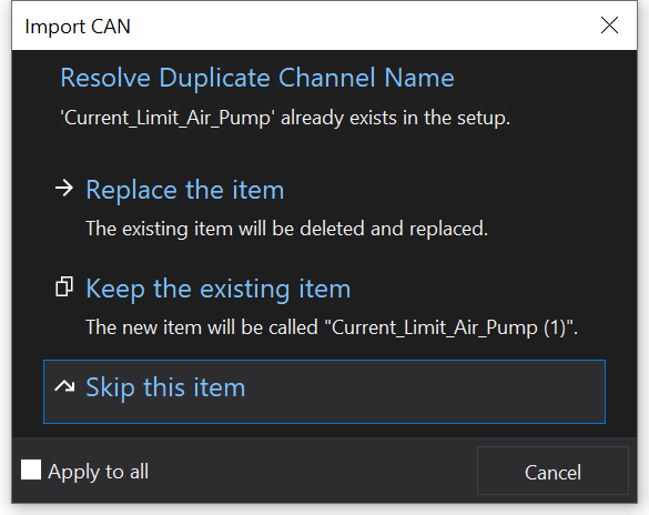
This shows the data for which there is a conflict and presents options to Replace, Keep (Rename), Skip or Cancel. By ticking the “Apply to all” box, any further duplicates will be treated in the same way without additional user interaction.
One the import has completed, the setup will include the new CAN channels with the signal name from the DBC file.
If the signal defines a text table for the various values of the signal, the signal table will display ‘Text’ in the Conversion column.
If the signal has a comment in the DBC file then this will be imported and the signal will have an information icon. Hovering over the signal will reveal the comment in a tool-tip.
To avoid conflict resolution when re-importing a DBC file, select “Replace CAN/DBC…” to replace signals by default.
The CAN (Controller Area Network) bus is a bus standard designed to allow devices to communicate with each other on a vehicle network. ECUs typically send data on specific CAN messages. Each CAN message has an ID (either 11 bits long or 29 bits long for extended identifiers) and consists of up to 8 bytes (64 bits) of data. By monitoring the CAN bus for specific message IDs, the display can receive and display data from the other ECUs.
For displays that support it, CAN-FD offers higher data rates and larger message sizes.
Configure the CAN port on the CAN Receive Tab , CAN Request Tab or CAN Transmit Tab .
The CAN port configuration options can vary depending upon whether the display supports CAN-FD.

CAN Port Configuration

CAN-FD Port Configuration
When CAN-FD is enabled, the data bitrate may also be specified.
A CAN network can run at various bit rates; however, all ECUs on a network must run at the same bit rate.
The display CAN bus speed must match that of the connected device for the CAN to work. To set the bus speed, select the required speed from the drop down list on the CAN Receive Tab , CAN Request Tab or CAN Transmit Tab .
For CAN-FD, an additional data bitrate may be specified. If set to ‘Disable CAN-FD’ then sending or receiving CAN-FD frames is disabled on the CAN Transceiver.
CAN-FD frames typically send the data payload with a higher bitrate to achieve higher bandwidth. While in theory this could be set as high as 8 Mbit/s, in practice this is rarely achievable and a lower speed such as 4 Mbit/s is recommended.
The CAN bus network must be terminated with 120 ohm load resistors at each end of the network. It is common for Engine Management Systems to have a load resistor fitted internally. Most displays have a software selectable load resistor that can be enabled in the setup if required; check the ‘Termination Resistor’ checkbox to enable it.
There are many forms of notation for defining the position of data in a message.
Dash Design considers each data byte in a message to have the most significant bit on the left and the least significant bit on the right.
The bit layout of a CAN frame is as follows:

CAN Message Bit Numbering
The CAN Message Layout view shows a visual representation of the layout of signals within a CAN message, which greatly simplifies the process of positioning signals.
Signals are extracted into data channels from CAN messages by specifying the start bit and bit-length of the data. The Start bit is specified as the least significant bit (lsb) of the least significant byte (LSB). For example, Byte 0 has a start bit of 0 and a length of 8. Byte 1 has a start bit of 8 and a length of 8 and so on. The least significant bit of a signal becomes the least significant bit in the extracted data channel.
Signal bit offsets need not be aligned to byte boundaries and can consist of less than 8 bits.
When dealing with multi-byte data, there are two common ways of representing numbers:
Because the start bit is specified as the least significant bit of the least significant byte, the byte order (endian) of the data affects the start bit. Consider a 16 bit number occupying the first two bytes of a message. In both cases, the length is 16 bits.
In Little Endian mode, the start bit is 0:

Little Endian Signal Layout
In Big Endian mode, the start bit is 8:

Big Endian Signal Layout
Note that lsb signifies Least Significant Bit and msb signifies Most Significant Bit. The arrow shows the direction from least significant data to most significant data.
Some ECUs send data in a multiplexed format. In this format, part of the message (often the first byte) is defined as the multiplexor. The other bytes in the message have different meanings depending on the value of the multiplexor.
For example, if the multiplexor is 0, Byte 1 could contain the current state of output 0 on a power management unit. If the multiplexor is 1, Byte 1 could contain the current state of output 1 and so on. In this way, ECUs that require transferring many parameters at a slow rate can do so with fewer message IDs, making it easier to manage the message IDs in the system as a whole.
The following table lists the start bit and length values for many common, byte aligned, data types and can be used a quick reference to simplify creating CAN setups.
The number following the value type indicates the position of the data within the 8 byte payload aligned to the size of the value type. For example, Byte 0 is on byte 0, Byte 1 on byte 1, Int16 0 is on bytes 0 & 1, Int16 1 is on bytes 2 & 3 etc.
The Byte order specifies LE for little endian and BE for big endian for multi-byte types.
| Value Type | Byte Order | Start Bit | Length | Description |
|---|---|---|---|---|
| Byte 0 | - | 0 | 8 | Byte 1 |
| Byte 1 | - | 8 | 8 | Byte 2 |
| Byte 2 | - | 16 | 8 | Byte 3 |
| Byte 3 | - | 24 | 8 | Byte 4 |
| Byte 4 | - | 32 | 8 | Byte 5 |
| Byte 5 | - | 40 | 8 | Byte 6 |
| Byte 6 | - | 48 | 8 | Byte 7 |
| Byte 7 | - | 56 | 8 | Byte 8 |
| Int16 0 | BE | 8 | 16 | Word 1 Big Endian |
| Int16 1 | BE | 24 | 16 | Word 2 Big Endian |
| Int16 2 | BE | 40 | 16 | Word 3 Big Endian |
| Int16 3 | BE | 56 | 16 | Word 4 Big Endian |
| Int16 0 | LE | 0 | 16 | Word 1 Little Endian |
| Int16 1 | LE | 16 | 16 | Word 2 Little Endian |
| Int16 2 | LE | 32 | 16 | Word 3 Little Endian |
| Int16 3 | LE | 48 | 16 | Word 4 Little Endian |
| Int32 0 | BE | 24 | 32 | Int 32, Byte 1 Big Endian |
| Int32 1 | BE | 56 | 32 | Int 32, Byte 5 Big Endian |
| Int32 0 | LE | 0 | 32 | Int 32, Byte 1 Little Endian |
| Int32 1 | LE | 32 | 32 | Int 32, Byte 5 Little Endian |
| Int64 | BE | 56 | 64 | Int 64 Big Endian |
| Int64 | LE | 0 | 64 | Int 64 Little Endian |
| Float 0 | BE | 24 | 32 | Float, Byte 1 Big Endian |
| Float 1 | BE | 56 | 32 | Float, Byte 5 Big Endian |
| Float 0 | LE | 0 | 32 | Float, Byte 1 Little Endian |
| Float 1 | LE | 32 | 32 | Float, Byte 5 Little Endian |
| Double | BE | 56 | 64 | Double Big Endian |
| Double | LE | 0 | 64 | Double Little Endian |
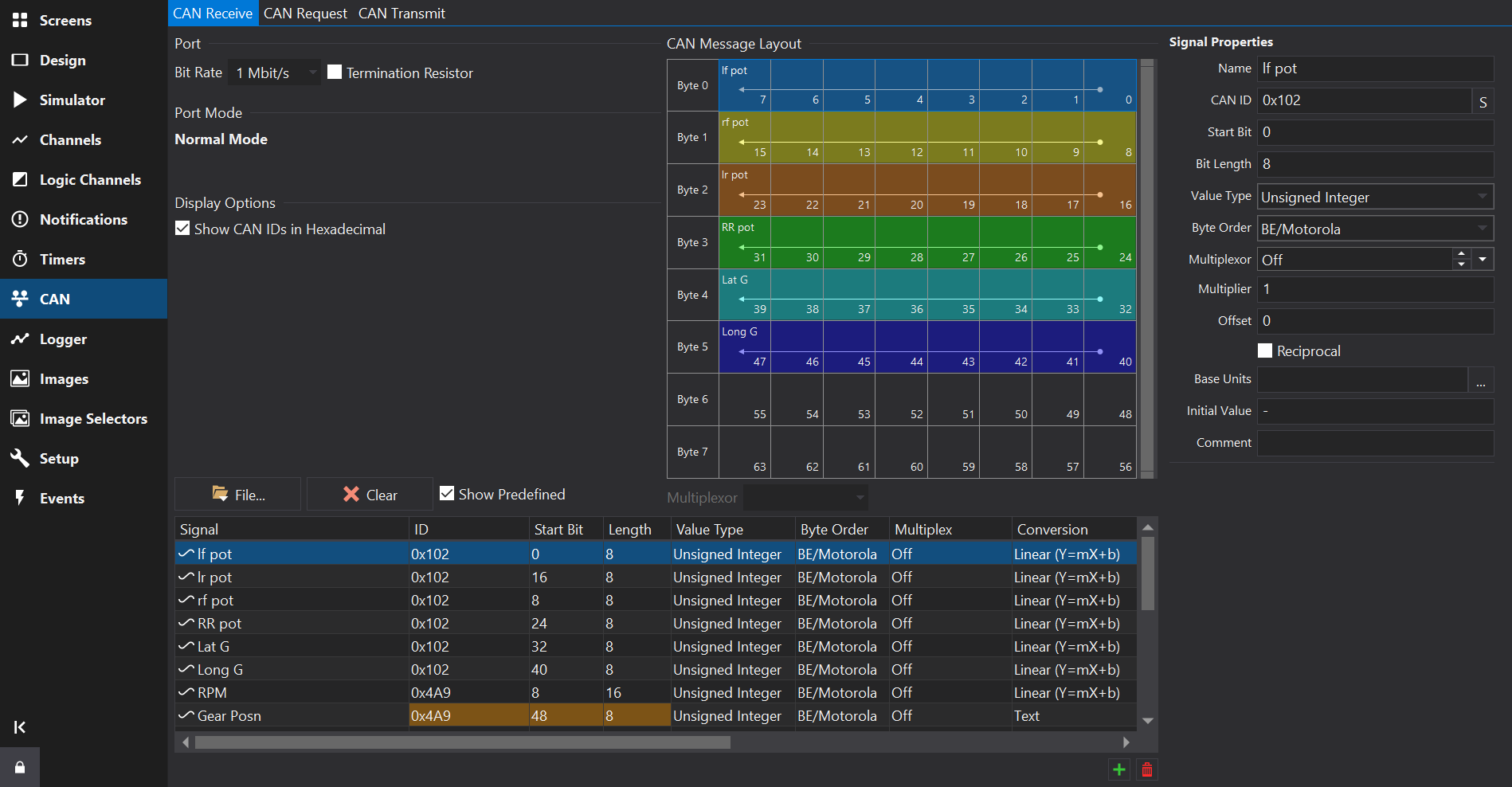
The CAN Receive Tab provides configuration of channels received via CAN messages.
At the bottom of the tab are the CAN frames and signals, represented as a unified list.
To the right of the tab is a CAN message layout view.
For displays with multiple CAN ports, the port may be selected via a drop-down box at the top-left of the tab. The signals table will only show signals configured for the selected port.
CAN Receive setup differs from prior versions of the software and will automatically add a scaled ‘output’ channel for the CAN source, effectively combining the signal decoder and the scaling.
CAN channels will also be viible on the Channels Tab .
Channels may be imported from Signal Database (.dbc) files using the Import… button. See CAN Signal Database (DBC) Import for further details on the import process.
It is not recommended to modify scaling after importing from a DBC file here - additional derived channels with different units / scaling may be added on the Channels Tab .
Towards the bottom right of the Signals Table, use the  button to add a new signal, and the
  button to remove the selected signal(s).
New signals will copy some fields from the currently selected signal, such as the CAN ID.
Press the ‘Clear’ button to remove all CAN signals / messages from the selected CAN port.
The signals table lists all the CAN signals configured to be received on the selected CAN port.
The context menu (right click) provides a command to show the selected signal in the Channels Tab .
The name of the CAN source. Clicking on the header at the top of this column will sort the table by name.
If the signal was imported from a DBC file and a comment was specified then signal will have an information icon. Hovering over the signal will reveal the comment in a tool-tip.
Multiple signals may be selected by holding down the Ctrl or Shift key while clicking on the signals.
Multiple selection allows editing of the selected signals collectively using the signals properties form to the right hand side of the view.
Some properties are not be available for editing in the properties form, for example channel scaling and filtering.
The CAN ID. This is specified as the right most 11 bits of a 16 bit value or the right most 29 bits of a 32 bit value for extended IDs.
If the Show CAN IDs as Hexadecimal box is checked, the IDs are shown and entered as hexadecimal numbers with an 0x prefix. Otherwise, they are shown and edited as a decimal number.
Clicking on the header at the top of this column will sort the table by CAN ID.
If the number has 3 hexadecimal digits then it is a standard ID, if it has 8 hexadecimal digits then it is an extended ID.
When entering CAN IDs into this column, use the ‘S’/‘E’ button to switch between standard or extended.
Note that an extended ID with the same value as a standard ID is NOT the same message and will not receive messages of the other ID type.
Makes this a CAN-FD message. In FD mode, higher start bit values are possible. CAN-FD enabled CAN ports only.
The start bit of the data. This is defined as the least significant bit of the least significant byte of the data. See CAN Message Overview for more information.
The length of the data in bits.
The type of the data. This can be one of the following values:
The byte order for multi-byte data. This can be either BE/Motorola (Big Endian) or LE/Intel (Little Endian). See CAN Message Overview for more information.
For non multiplexed data, this should be set to Off. Otherwise it can be set to Multiplexor if this value controls the multiplexing or a number (m=0, m=1, m=2 etc) which is the value of the Multiplexor at which this value is valid. See CAN Message Overview for more information.
The conversion (scaling) type from the raw CAN data to a value or textual representation. Click the ‘…’ button to open a scaling editor.
If the signal was imported from a DBC file, and you want to change the scaling to a different unit then it is best to set the input units of the signal and a display unit or create a derived channel to rescale from the imported DBC values.
Multiplier to convert from a raw signal value to a physical value.
Phys = (Raw * Scalar) + Offset.
Offset to convert from a raw signal value to a physical value (added to the value after multiplying).
Phys = (Raw * Scalar) + Offset.
Not commonly used but changes the scaling equation to Phys = (Raw / Scalar) + Offset.
Units of the scaled physical value of this signal. To convert to other units, add a channel on the Channels Tab and select a unit conversion after setting the input to this CAN channel.
Sets the initial value of the CAN output. This is the raw value. For example, for a CAN output of RPM_Raw used in an output to create RPM with a x2 scalar, the raw value for 2000 RPM would be 1000. To clear the initial value, set this to ‘-’. When importing from a dbc file, the “GenSigStartValue” attribute will be used to set the initial value.
Filters may be applied to the CAN channel here such as controlling the behaviour when messages stop being received or providing an ‘Error Text’ value.
Signals that share the same bits and are not multiplexed will show a different background colour in the ID, Start Bit and Length fields. This is allowed but normally a configuration error; the colouring is intended to assist in spotting such errors easily. See the Gear Posn signal in the above screenshot for an example.
Selecting a signal in the signals table will display all signals in the same CAN frame (signals with the same CAN ID) in this view.
The Multiplexor drop-down box will be enabled if it is a multiplexed frame and will allow selection of one of the configured multiplexor values. When selected, this will only display signals in the view that are present when the multiplexor signal has this value.
For CAN-FD frames, the zoom-bar to the right of the CAN message layout view allows zooming and scrolling of the message view.
The CAN Request Tab provides a way to send out fixed CAN messages at regular intervals or in response to another CAN message.
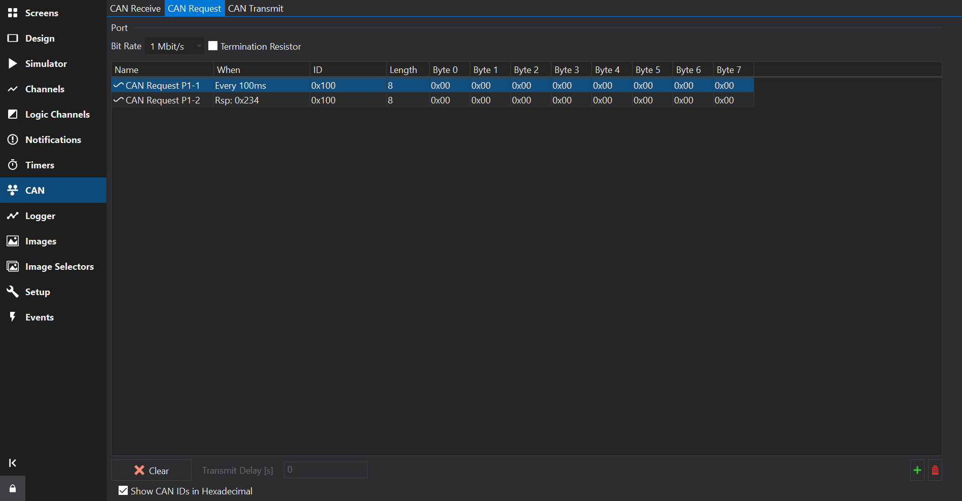
Towards the bottom right of the Messages Table, use the button to add a new message, and the button to remove the selected messages(s).
The CAN Transmit Tab provides a way to send out CAN messages that contain values from channels or special values such as firmware version or setup name.
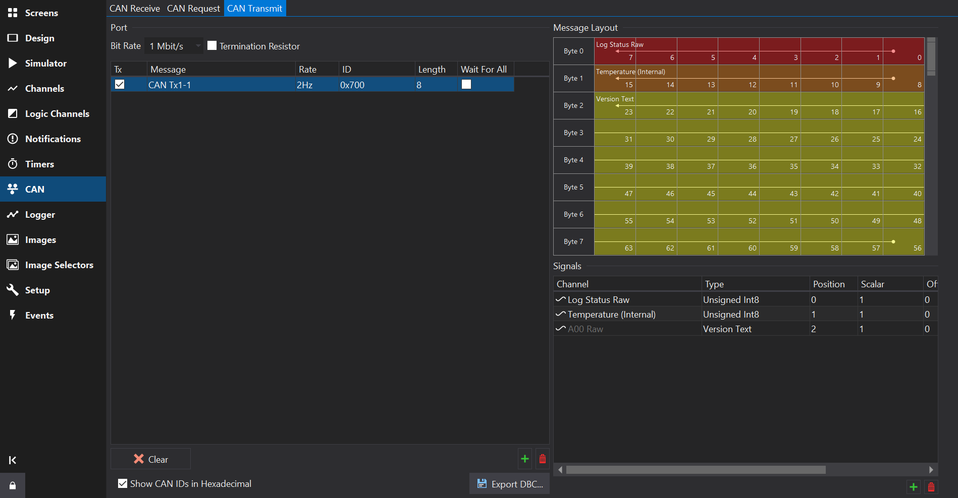
Towards the bottom right of the Messages Table, use the button to add a new message, and the button to remove the selected messages(s).
Enables the message. IF unchecked then the message will not be sent by the display.
Name of the message.
Rate at which the message is repeatedly sent.
The CAN ID. This is specified as the right most 11 bits of a 16 bit value or the right most 29 bits of a 32 bit value for extended IDs.
If the Show CAN IDs as Hexadecimal box is checked, the IDs are shown and entered as hexadecimal numbers with an 0x prefix. Otherwise, they are shown and edited as a decimal number.
Clicking on the header at the top of this column will sort the table by CAN ID.
If the number has 3 hexadecimal digits then it is a standard ID, if it has 8 hexadecimal digits then it is an extended ID.
When entering CAN IDs into this column, use the ‘S’/‘E’ button to switch between standard or extended.
Note that an extended ID with the same value as a standard ID is NOT the same message and will not receive messages of the other ID type.
Makes this a CAN-FD message. In FD mode, higher start bit values are possible. CAN-FD enabled CAN ports only.
For CAN-FD messages, sets the Bit Rate Select flag. CAN-FD enabled CAN ports only.
Specifies the Data Length Code of the channel, i.e. the size of the data packet of this ID in bytes. This can be anywhere between 0 and 8 bytes; by default it is set to the maximum size of 8 bytes. For CAN-FD messages this can go up to 64 bytes.
If the Wait For All column is ticked, then the CAN message will only be transmitted once all the inputs to the message (see below) are valid. Inputs such as analogue channels are valid immediately but for data coming via CAN or serial, the outputs are not valid until they have been received at least once.
If the Wait For All column is not ticked, then the message will be transmitted immediately; any sections of the message where the inputs are not valid will be zero.
Towards the bottom right of the Signals Table, use the button to add a new signal, and the button to remove the selected signal(s).
A message must be selected in the Messages Table to be able to add signals.
Channel that will be packed into the CAN signal.
Data type and byte order for the raw signal value. The data type affects the size of the signal.
Some data types are special and do not require a channel (e.g. Display Serial Number).
When using a special data type such as Serial Number, some display firmware versions still require a Channel to be selected or the transmitted signal value will be zero.
Byte position of the first byte in the CAN frame that the signal occupies
Scalar used to convert the Physical Channel value to a raw value. This is specified as if converting from raw => physical.
Phys = (Raw * Scalar) + Offset
i.e.
Raw = (Phys - Offset) / Scalar
Offset used to convert the Physical Channel value to a raw value. This is specified as if converting from raw => physical.
Units of the Physical value. If the input channel uses different units then Dash Design will insert additional scaling to convert from the Channel units to the Physical units prior to applying the Scalar and Offset.
By specifying the expected physical units here, if the source channel units are subsequently changed then the scaling change will automatically be accounted for, so the transmitted data should still be of the correct magnitude.